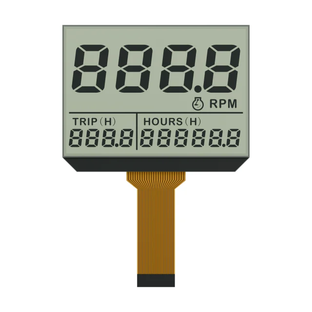
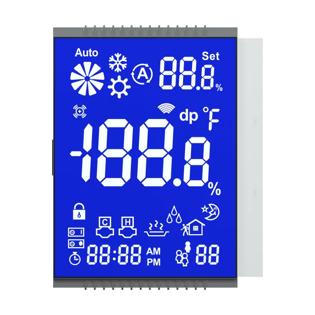
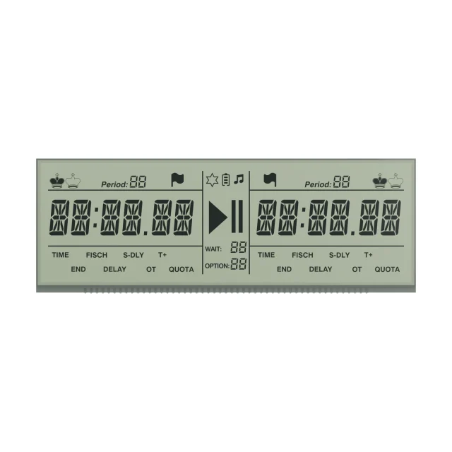
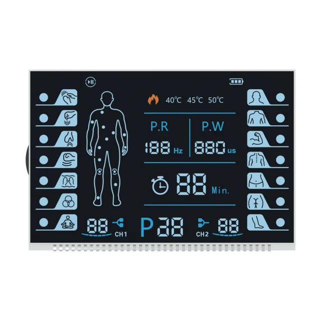
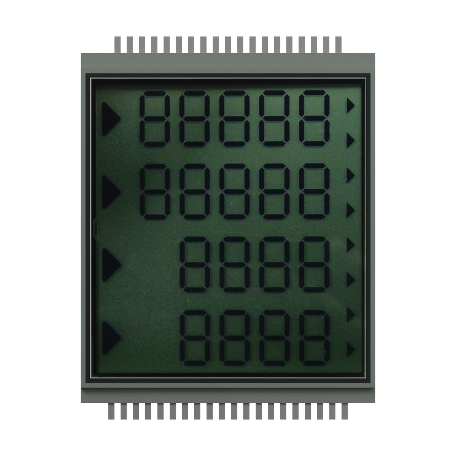
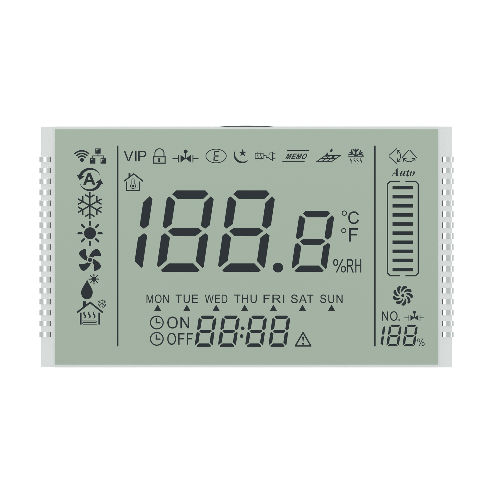
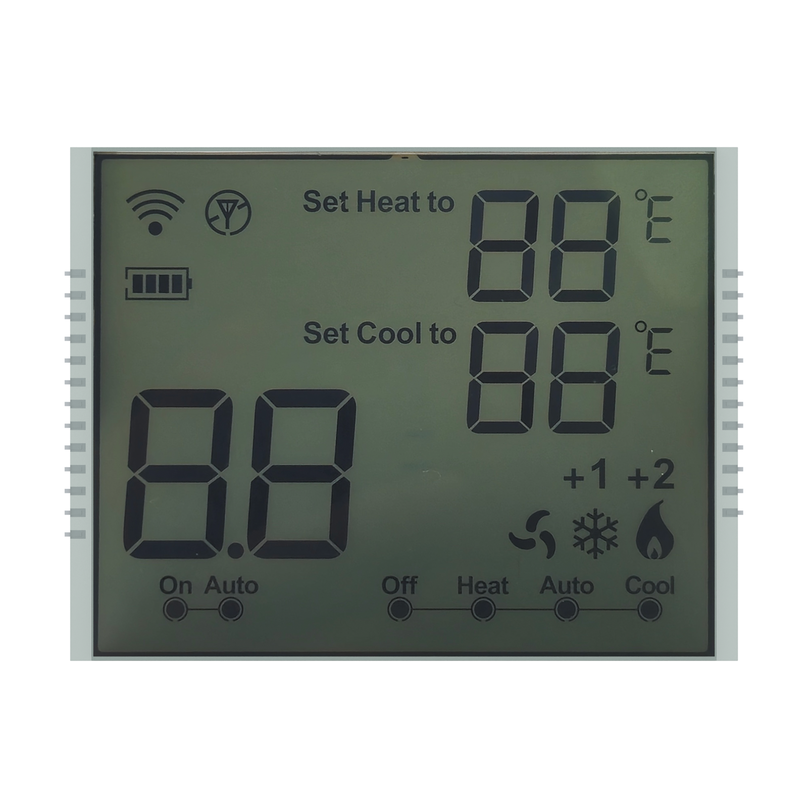
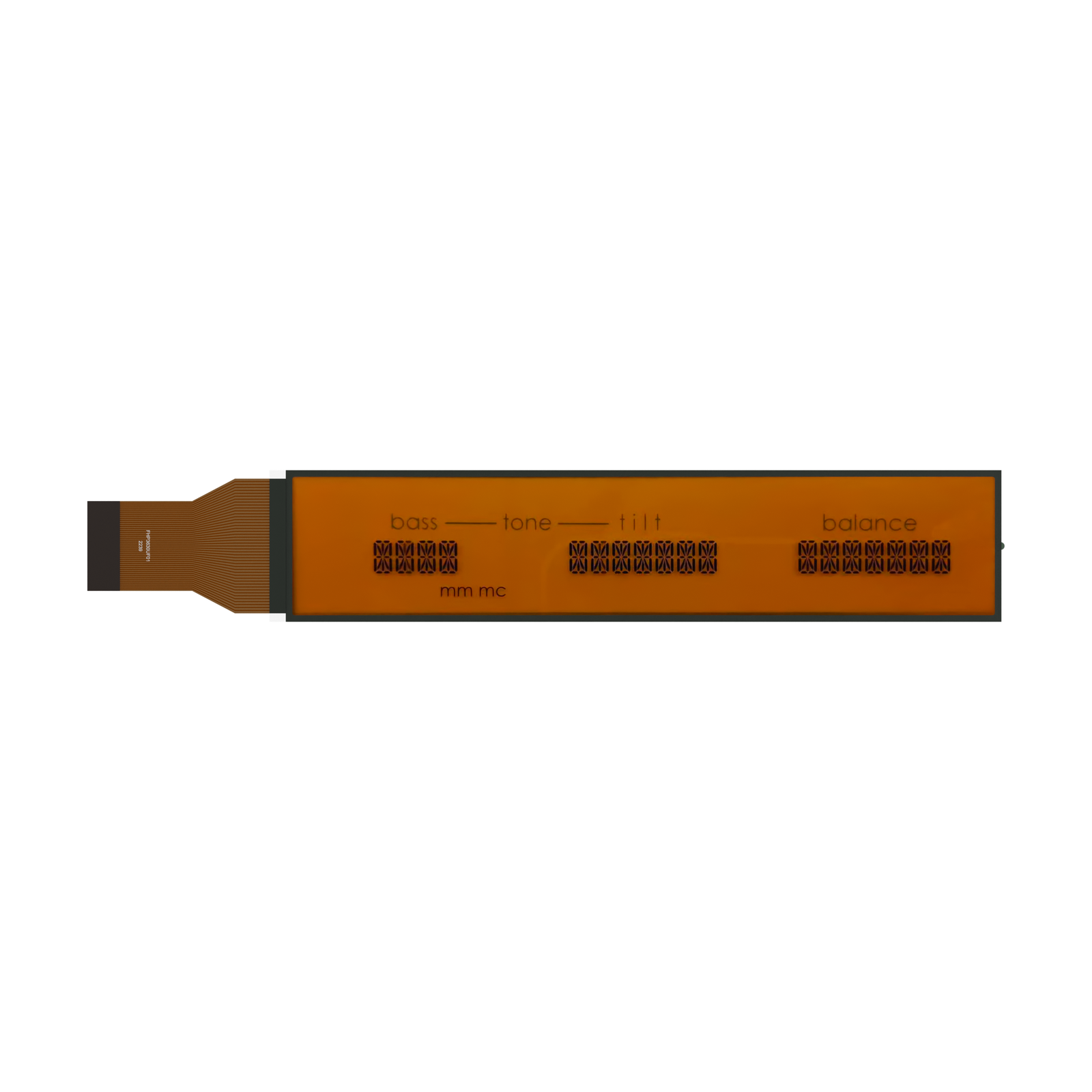
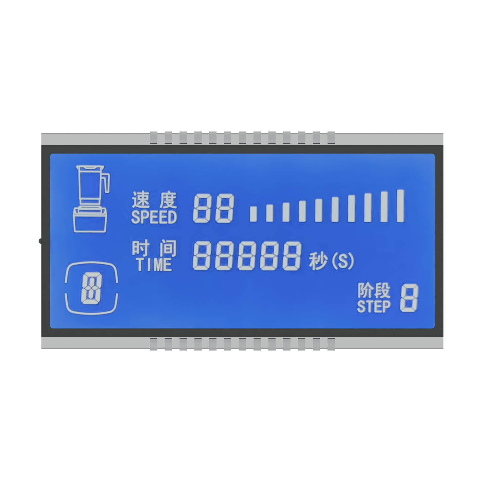
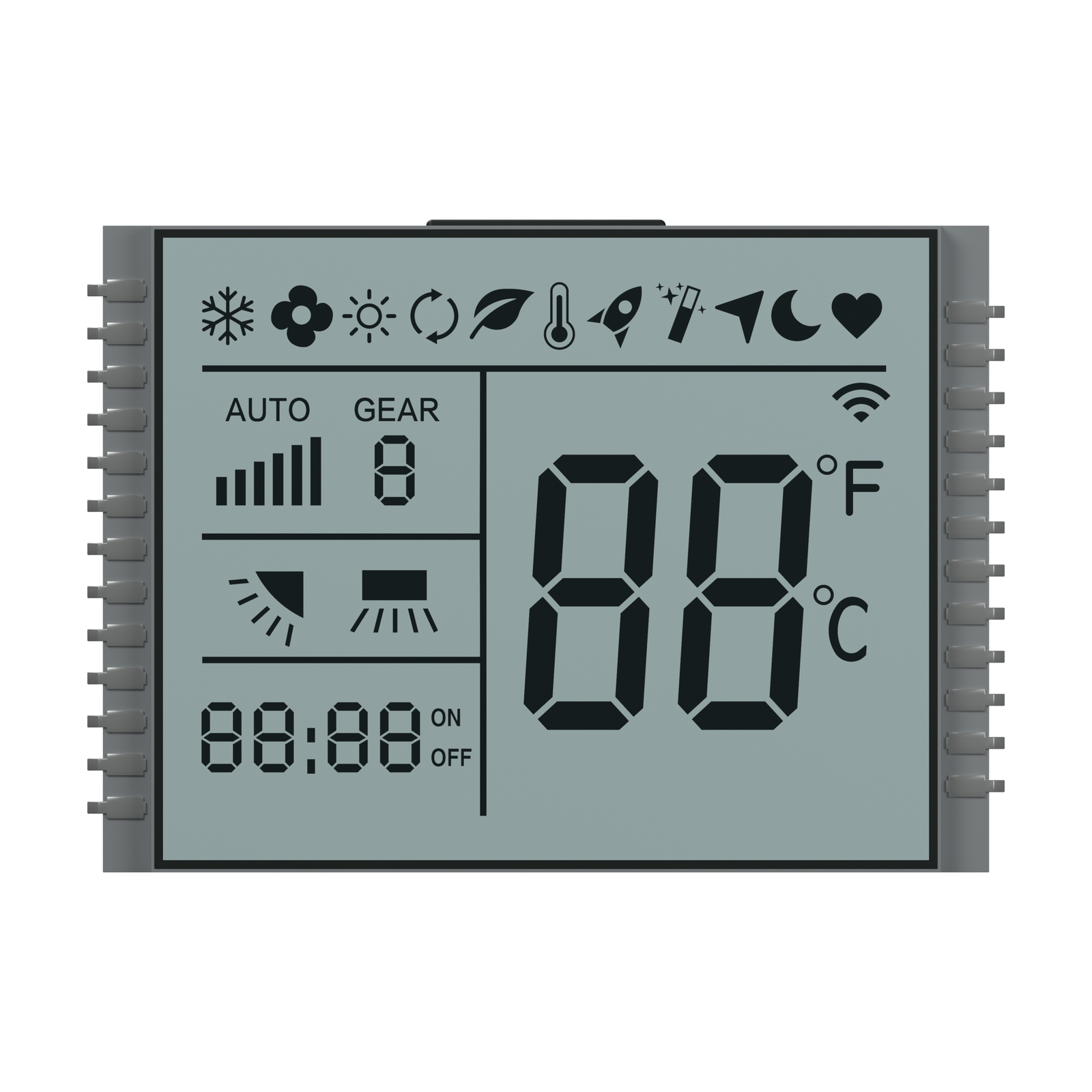
Mono LCD and LCM modules

Monochrome LCD Module Manufacturer for OEM Projects

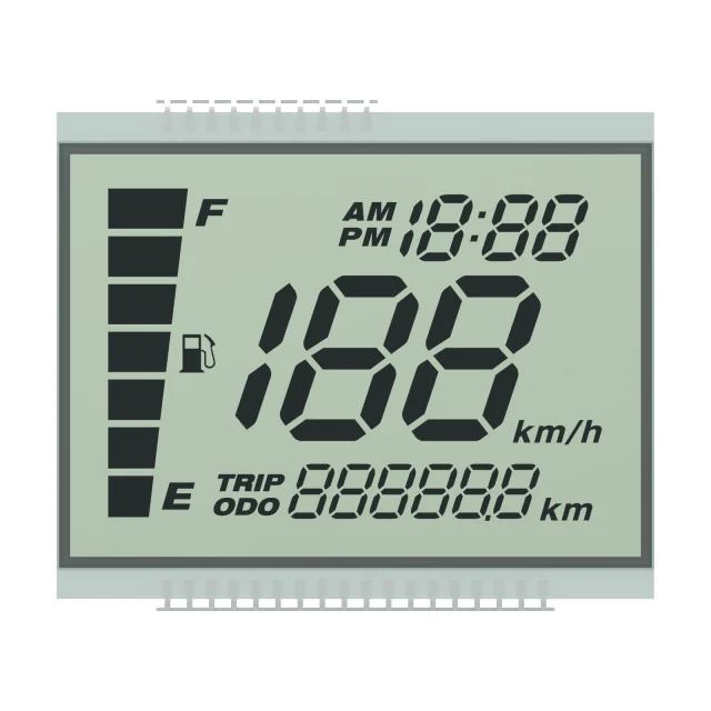
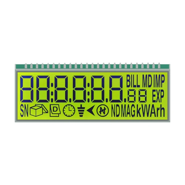
Custom segment LCD, dot matrix LCD and LCM module support for meters, instruments, controls, medical devices, automotive panels and handheld products.

TN / HTN / STN / FSTN / VADisplay mode review
COG / COB / TABAssembly structure options
Segment + dot matrixLayout customization
Metering / HMI / automotiveApplication fit

Product paths

Choose the Mono LCD Structure First

Mono LCD projects usually start with display mode, viewing condition, driving method and assembly structure. These choices affect readability, power use, tooling and long-term supply.

Common path

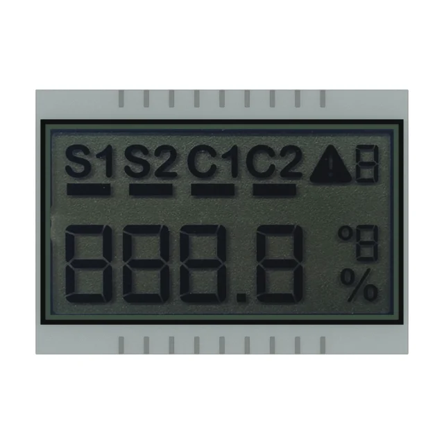
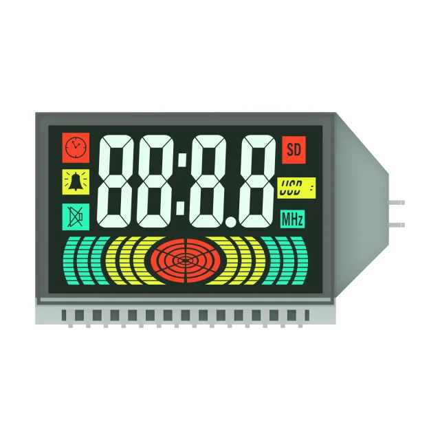
Segment LCD

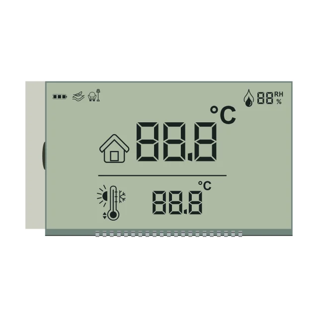
For fixed icons, digits, meters, thermostats, controllers and products that need clear status information.

Common path

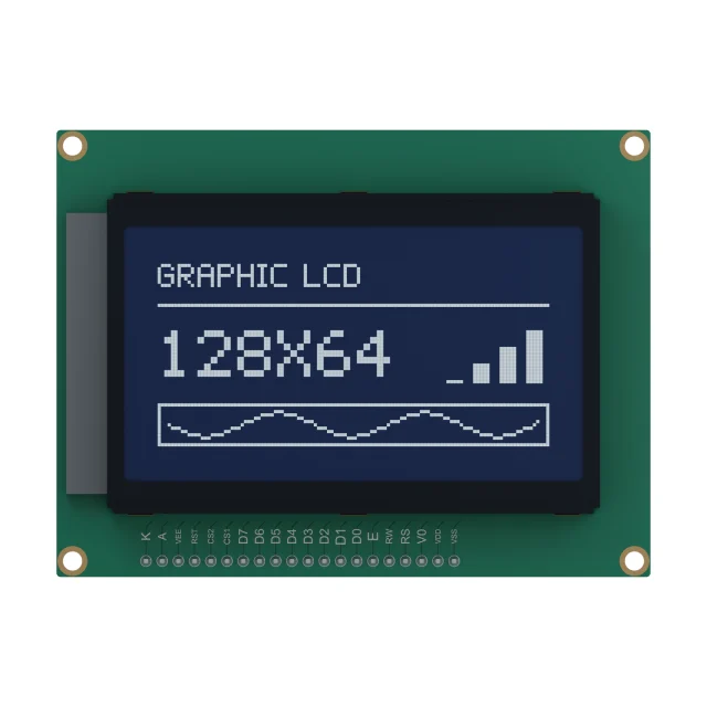
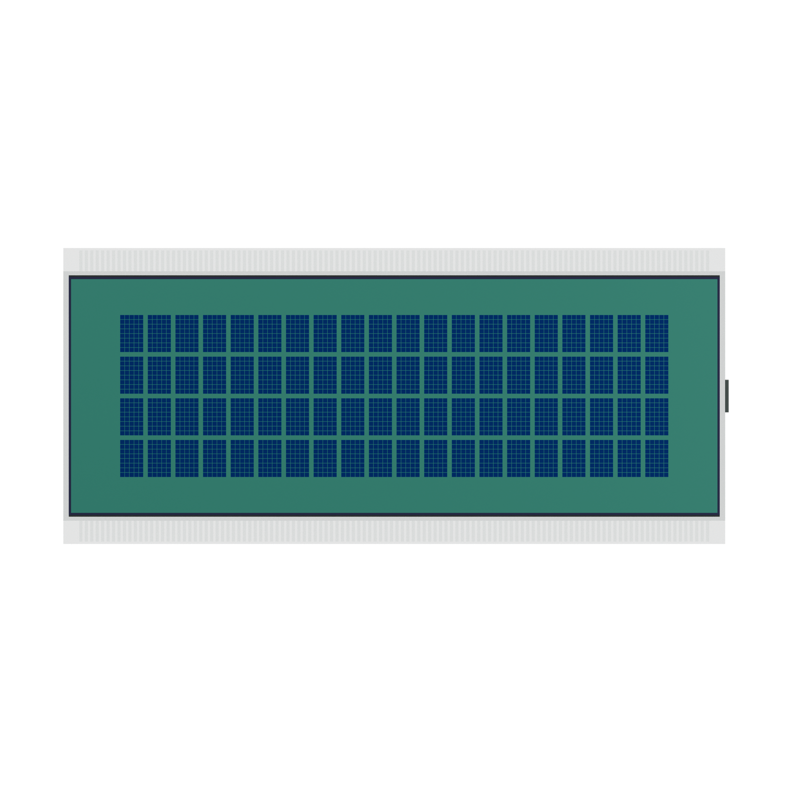
Dot Matrix LCM

For text, simple menus, symbols and mixed content where a controller board or module structure is needed.

Visual path

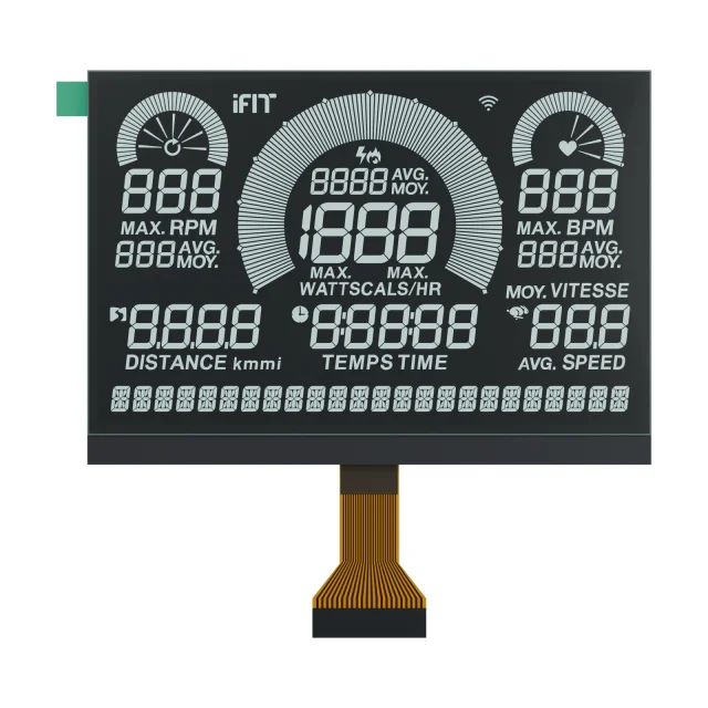
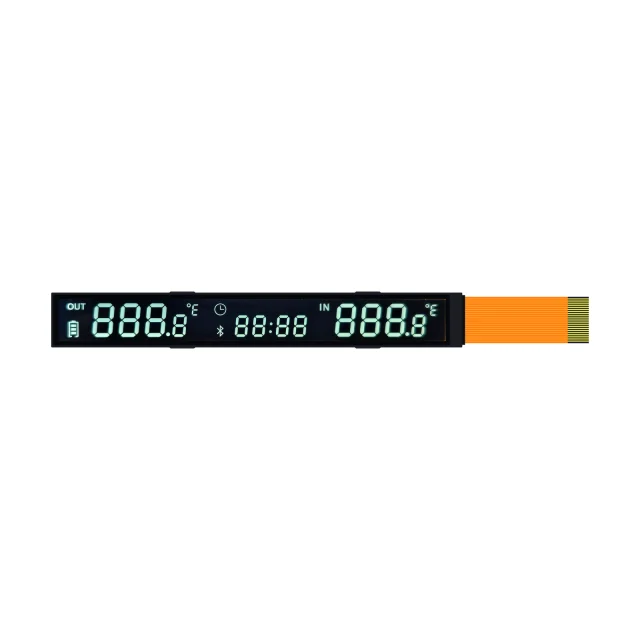
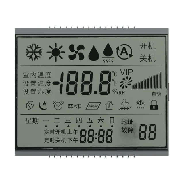
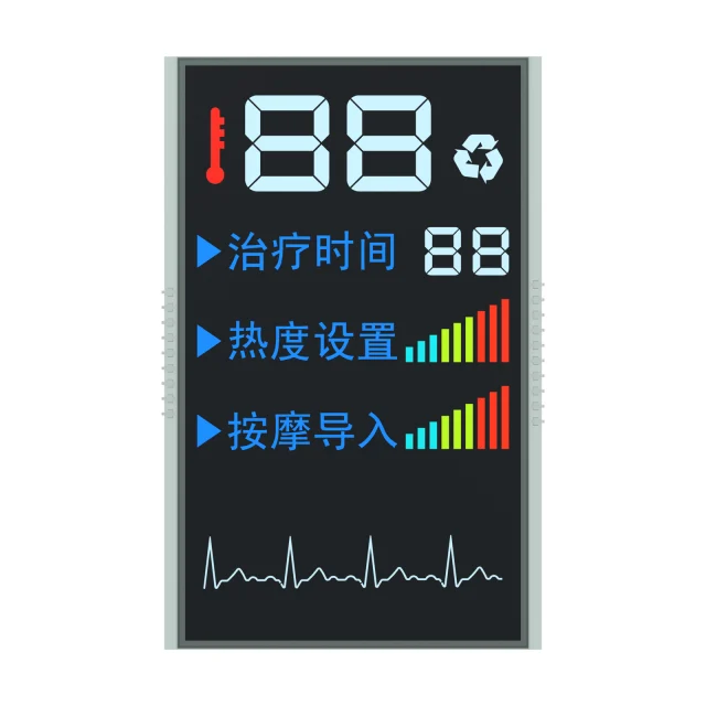
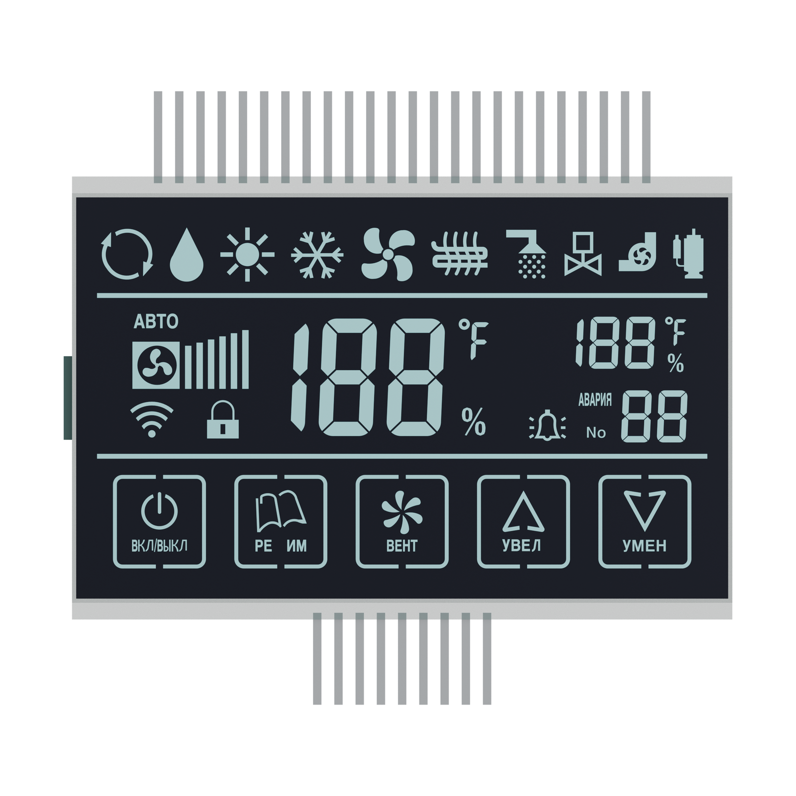
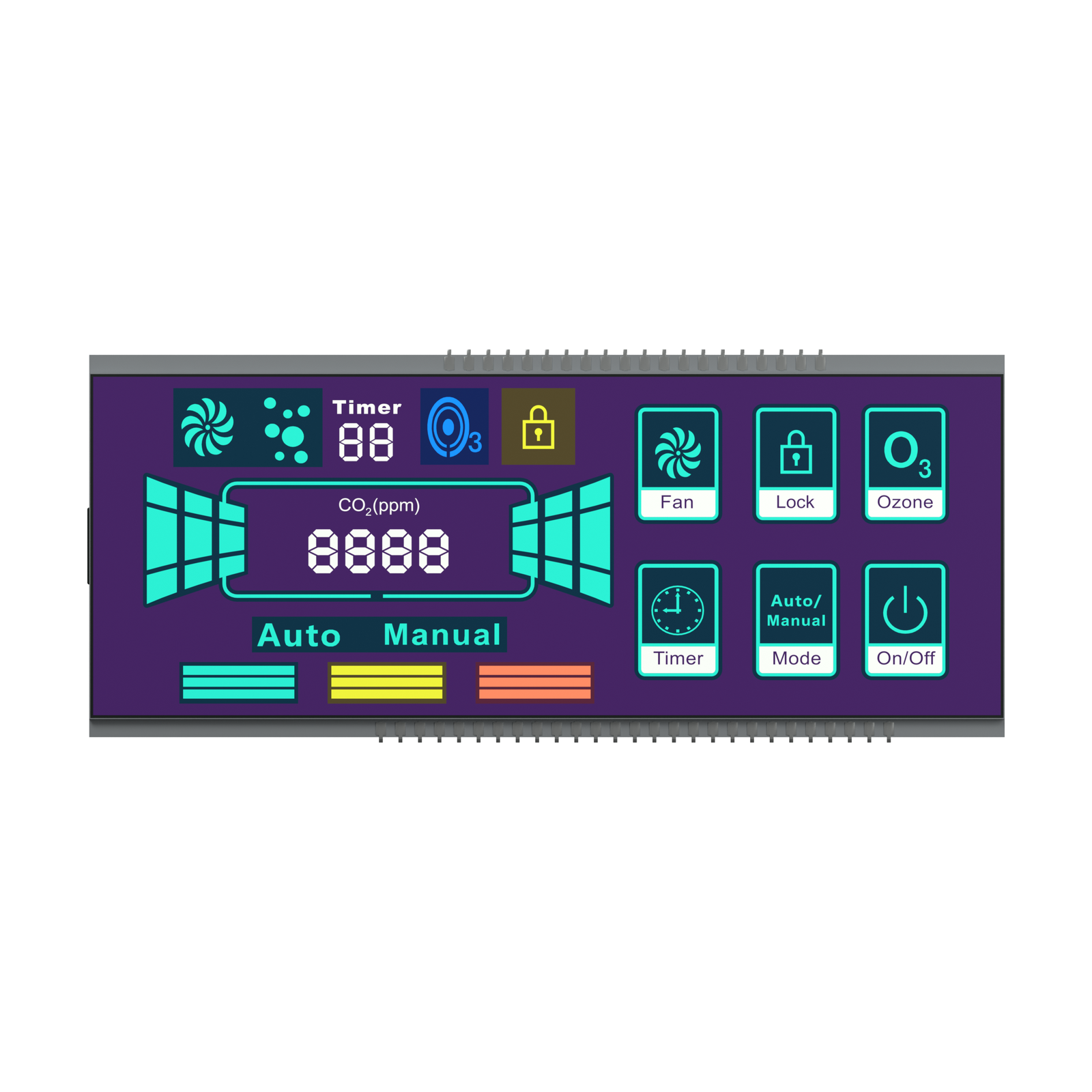
VA High Contrast LCD

For black-background displays, automotive panels, appliances and user interfaces that need strong contrast.

Assembly path
Assembly path

COG / COB / TAB LCM

For products where thickness, PCB layout, connector routing, durability or enclosure space drives the design. For driver-on-glass projects, review our custom COG LCD display module capability.

For products where thickness, PCB layout, connector routing, durability or enclosure space drives the design.

Engineering scope

Mono LCD Details to Confirm Before Tooling

A custom mono LCD is shaped by display mode, glass outline, duty and bias, viewing direction, backlight, connector and environmental requirements.

  • Display modeTN, HTN, STN, FSTN, DFSTN, VA or FSLCD direction.
  • Display contentSegment icons, digits, dot matrix area or mixed layout.
  • Assembly structureCOG, COB, TAB or custom LCM module format.
  • Electrical designDuty, bias, driving voltage, IC selection and connector pinout.
  • Glass and outlineGlass size, view area, thickness, drilling, cutting and mounting limits.
  • Optical requirementPositive or negative mode, polarizer, backlight and viewing direction.
  • Use environmentIndoor, outdoor, vehicle, medical, industrial or handheld conditions.
  • Supply planningSample stage, tooling, expected volume and lifecycle requirement.
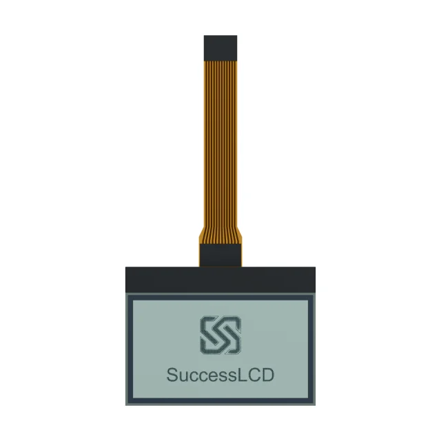
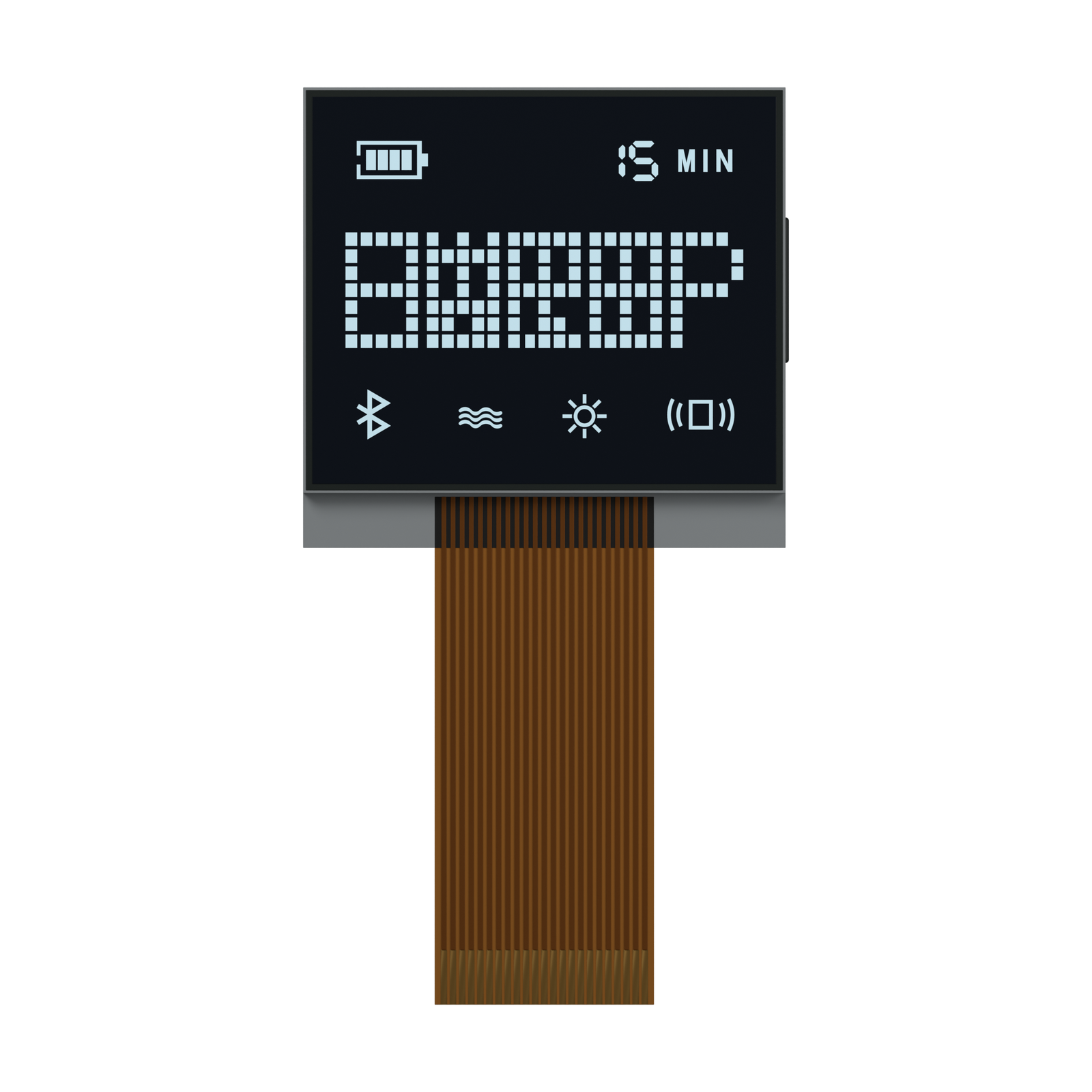
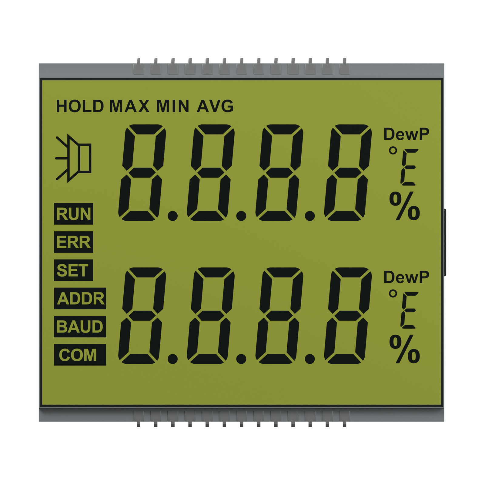
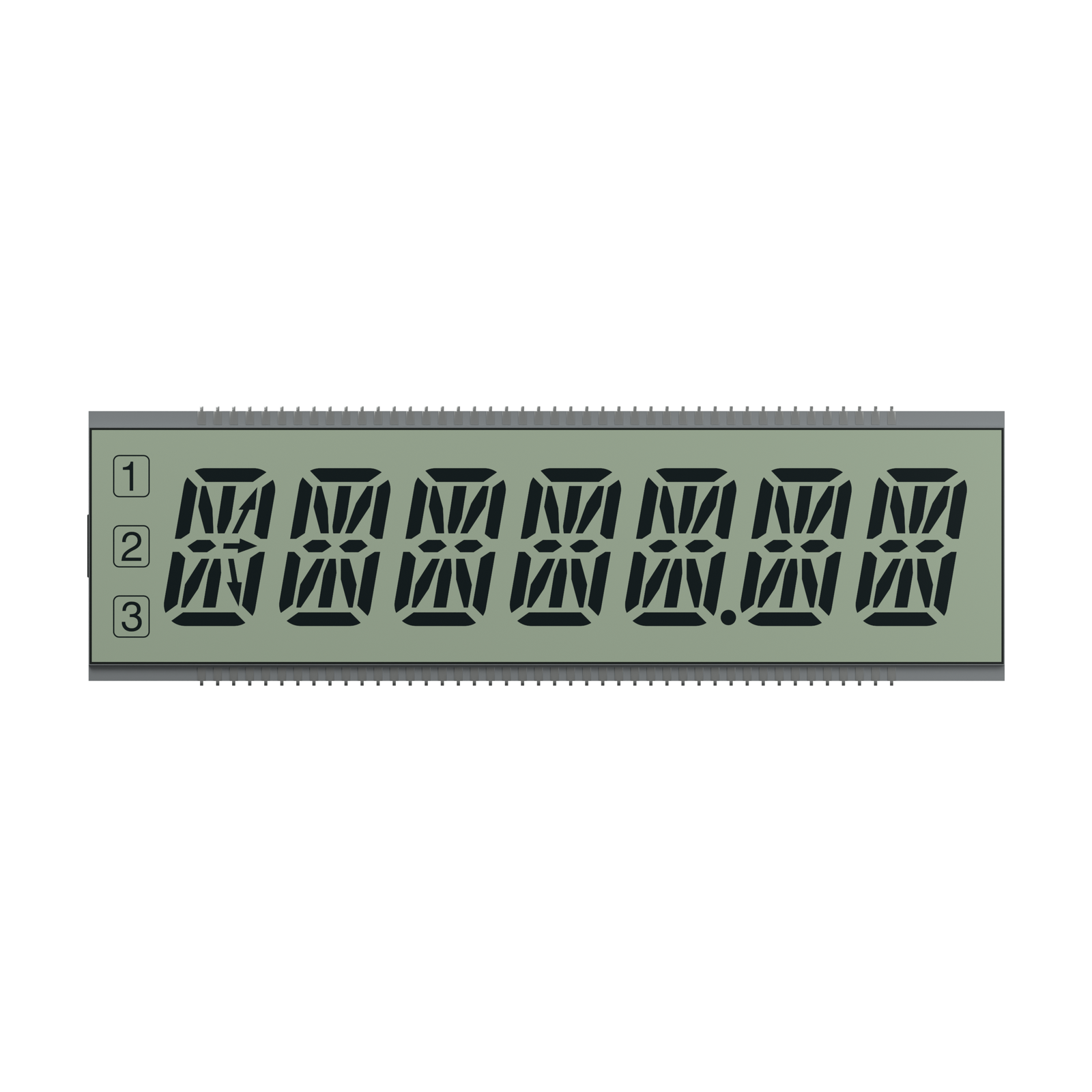
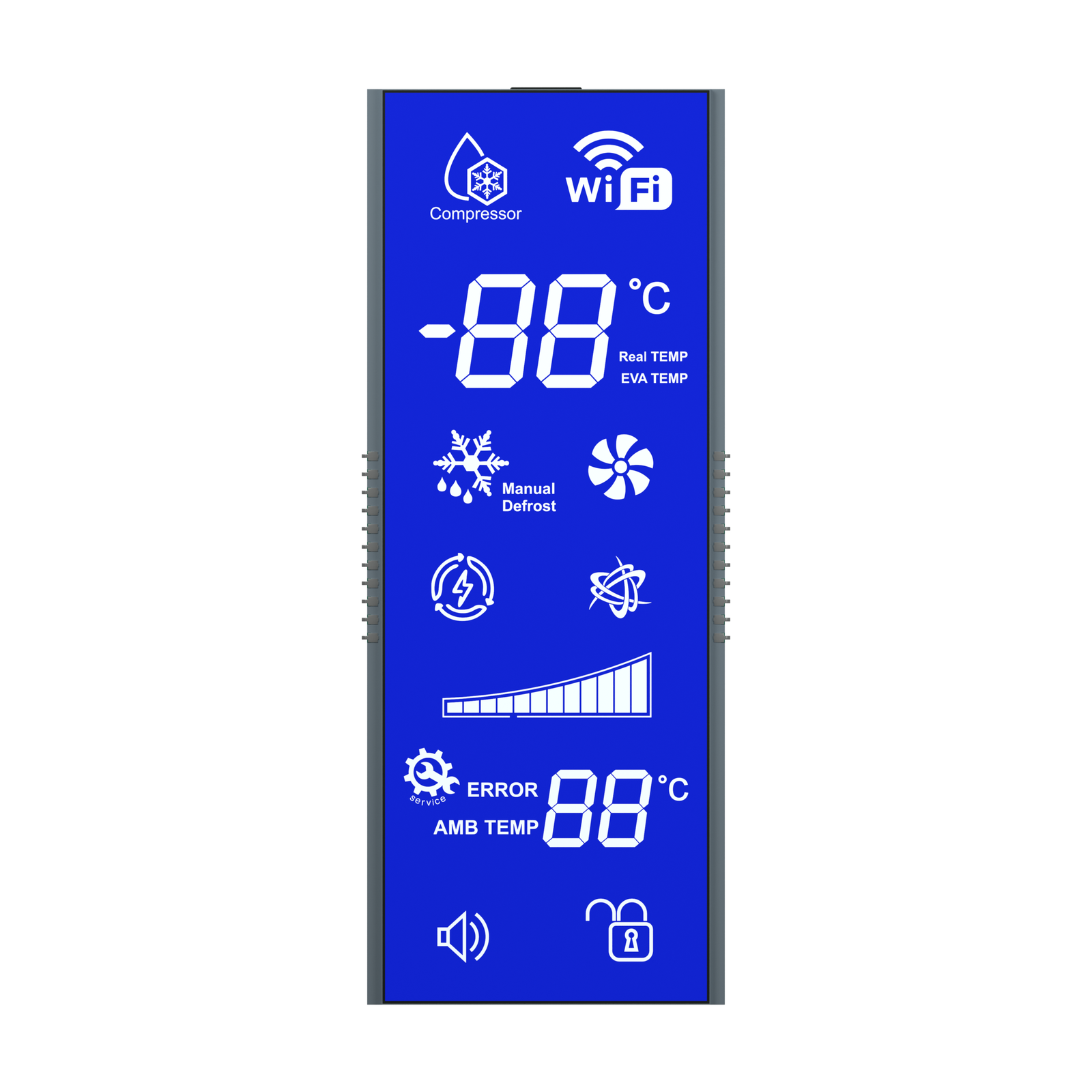
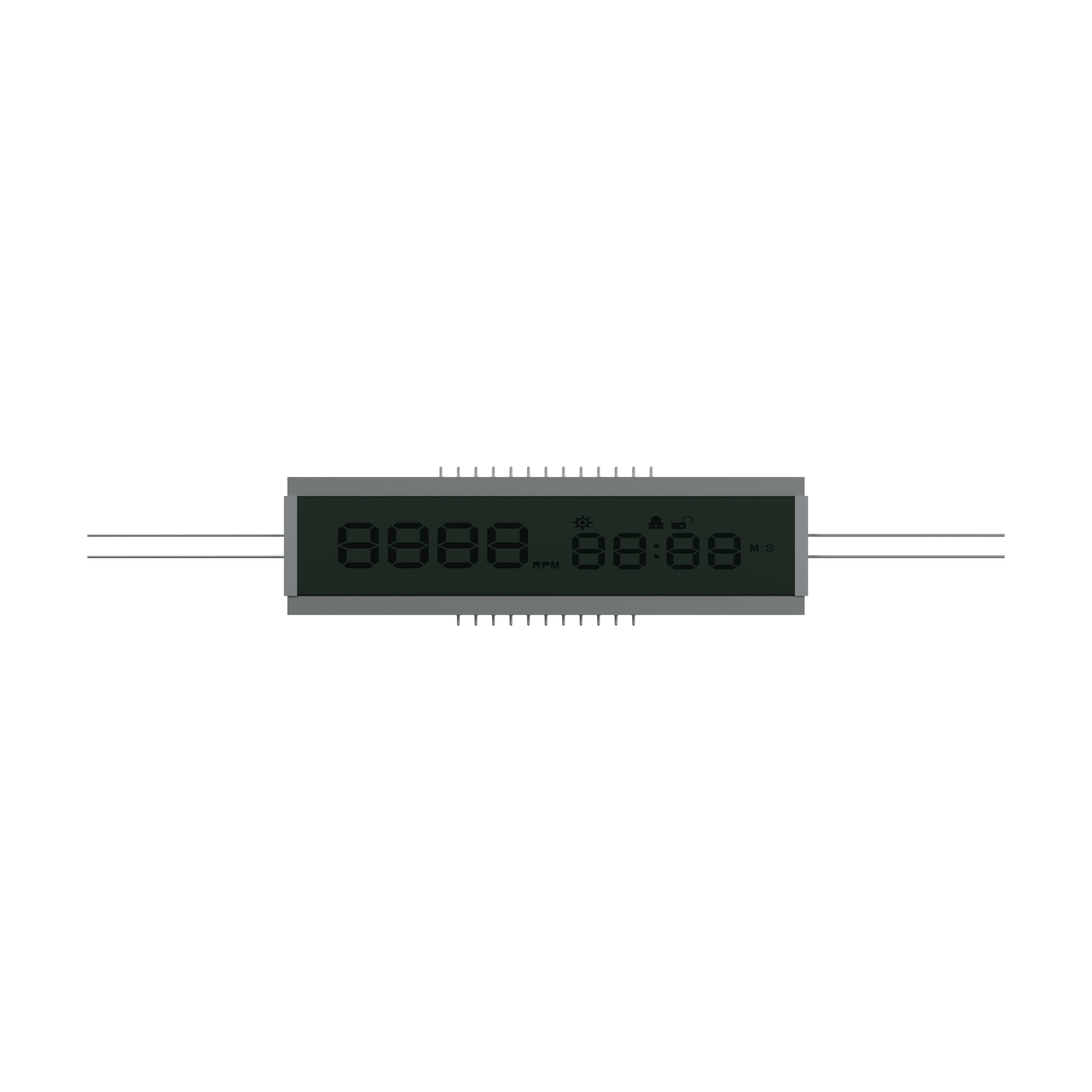
Mono LCD and LCM module structure example

Display options

Representative Mono LCD Configurations

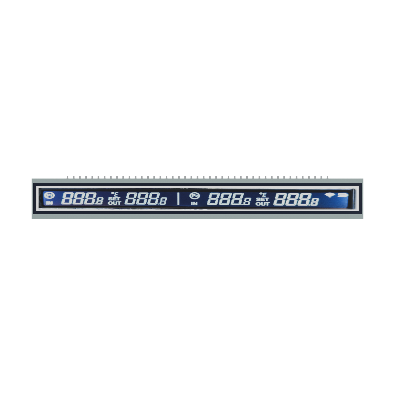
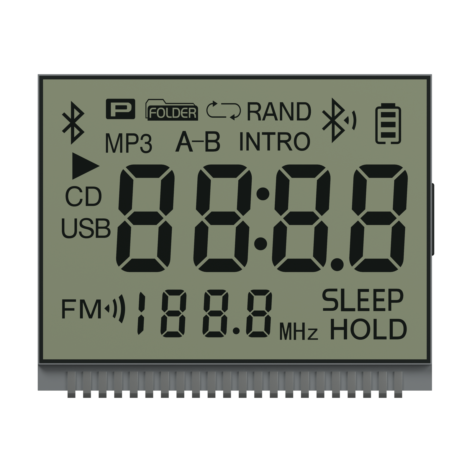
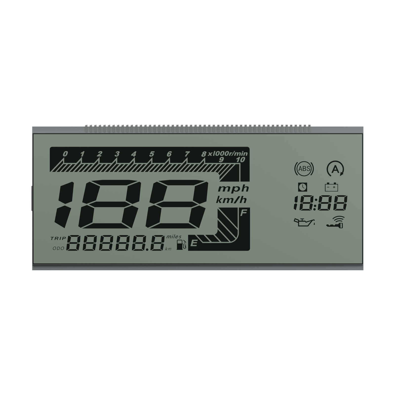
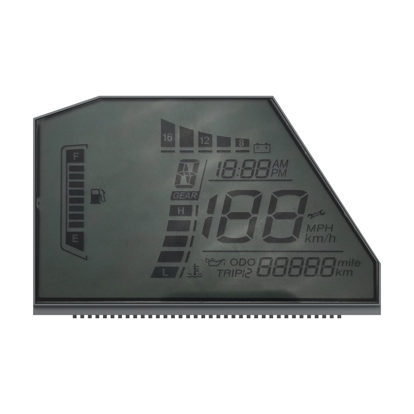
These cards are selection directions, not verified catalog models or production records. Final glass outline, icon layout, viewing mode, connector, backlight and published asset provenance require project review.

01
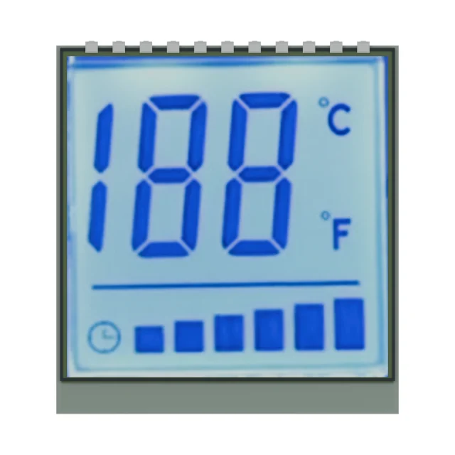
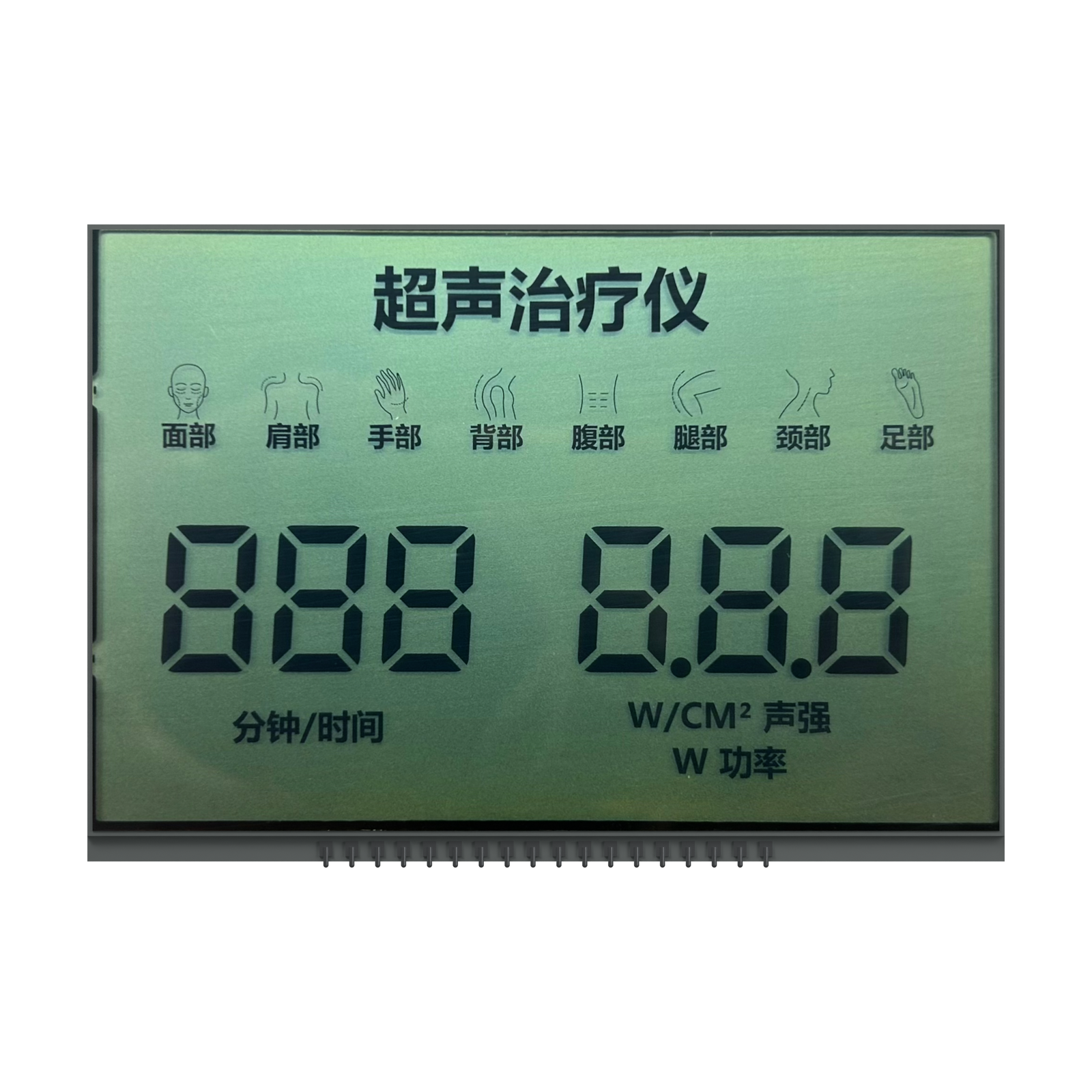
TN positive segment LCD example

TN Positive Segment

SegmentCost-sensitive
02
HTN negative LCD example

HTN Negative LCD

Negative modeHigher contrast
03
STN yellow green LCD example

STN Yellow Green

STNMatrix display
04
STN blue mode LCD example

STN Blue Mode

Text displayControl panel
05
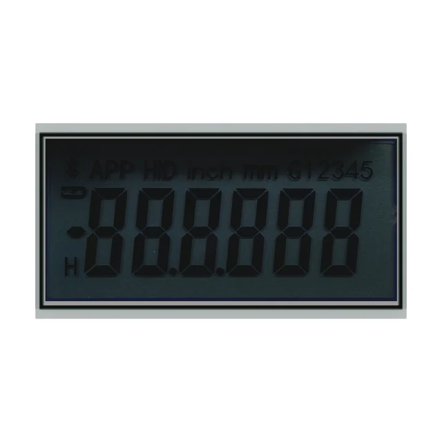
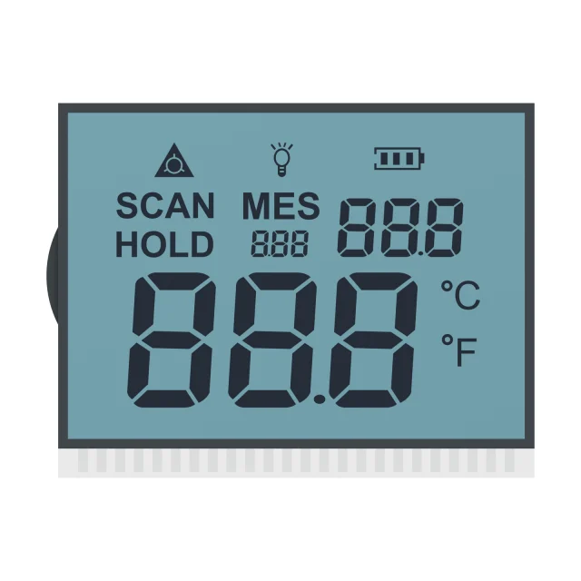
STN grey mode LCD example

STN Grey Mode

Neutral backgroundMetering
06
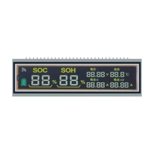
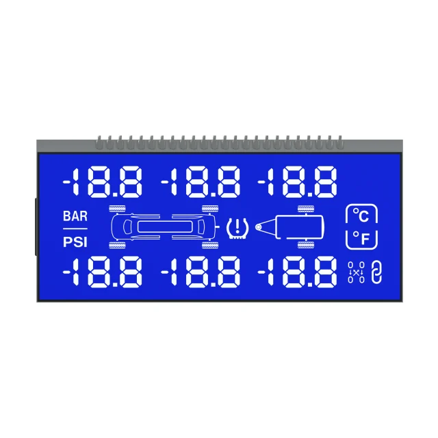
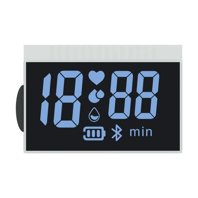
VA high contrast LCD example

VA High Contrast

Black backgroundStrong contrast
07
VA LCD with silk screen icons

VA With Silk Screen

Custom iconsPrinted mask
08
FSLCD color display example

FSLCD Color Display

Color sequenceCustom effect
09
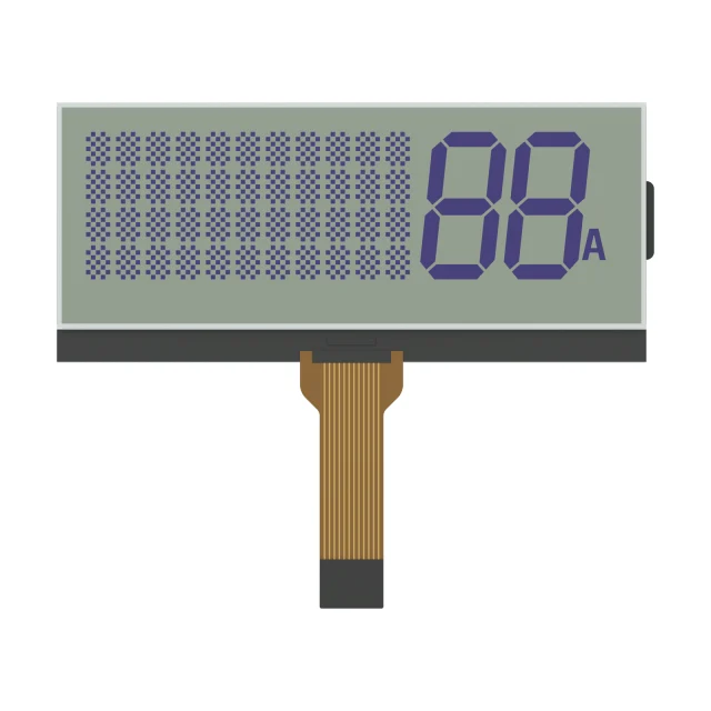
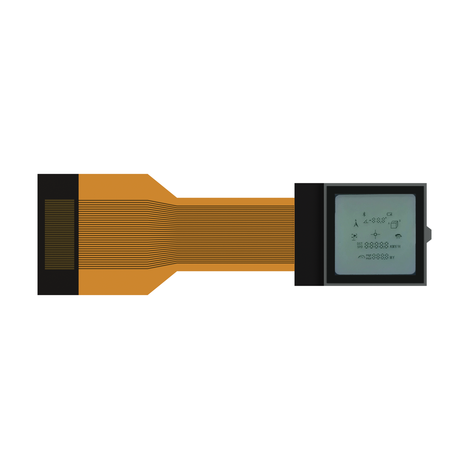
Segment and dot matrix LCD example

Segment + Dot Matrix

Mixed contentHandheld device
10
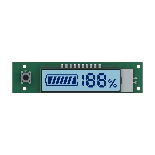
Custom LCM module example

Custom LCM Module

Module assemblyEmbedded system
11
Outdoor VA LCD example

Outdoor VA LCD

Outdoor useReadability review
12
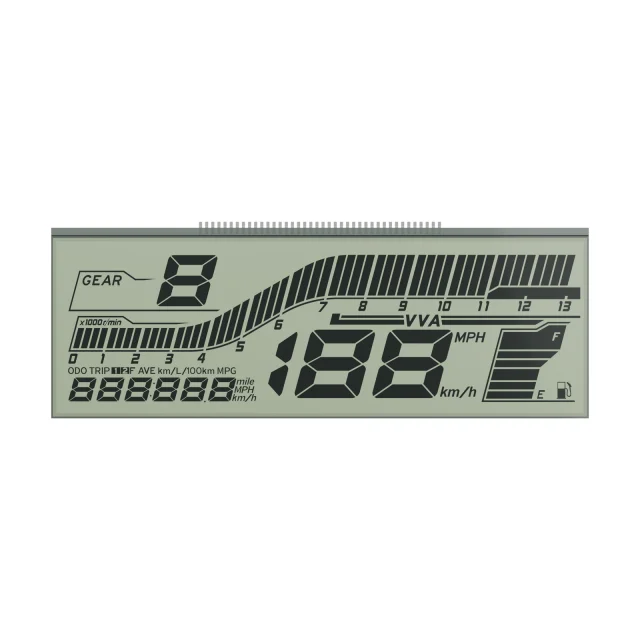
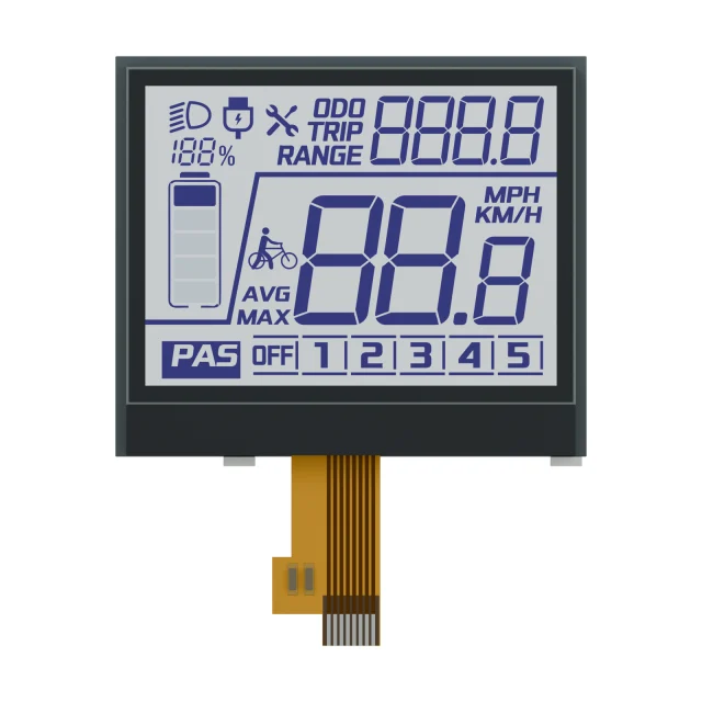
Automotive VA LCD display example

Automotive VA LCD

Vehicle panelInstrument display

Selection guide

Mono LCD or TFT LCD?

Mono LCD fits projects where fixed information, low power, custom glass shape or long-term display consistency matter more than color graphics.

Decision Point Mono LCD / LCM TFT LCD Module
Display content Digits, icons, symbols, simple text and fixed layouts. Color graphics, images, icons, menus and richer UI layouts.
Power profile Power depends on drive method, content, backlight use, update behavior and operating conditions; compare both options against the project power budget. Power depends on panel operation, backlight, content, update behavior and operating conditions; compare both options against the project power budget.
Mechanical shape Custom glass can support project-specific outline, icon and window geometry within reviewed manufacturing rules. Usually based on rectangular active area and standard module frame.
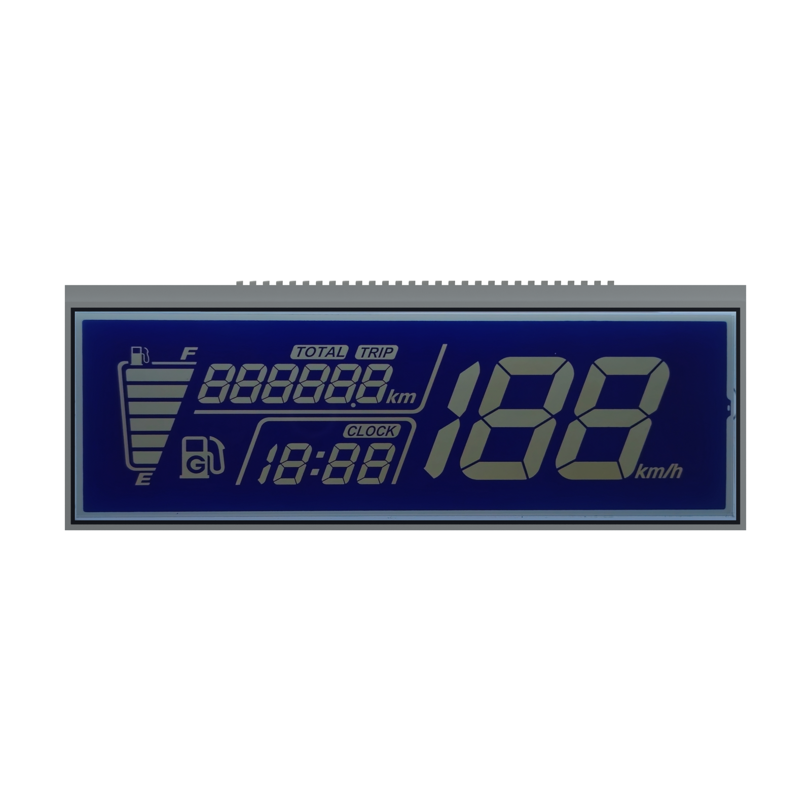
Use case Meters, appliances, controls, instruments, vehicle panels and devices with fixed information requirements. Industrial HMI, medical screens, smart devices and visual control panels.

RFQ preparation

What to Send for a Mono LCD Review

A clear request helps identify the right LCD mode, IC direction, tooling scope and module structure.

Display Layout

Segment drawing, icon list, dot matrix area, view area, glass outline and target appearance.

Electrical Requirements

Duty, bias, driving voltage, controller preference, pinout, connector and backlight needs.

Application Conditions

Operating environment, viewing direction, product enclosure, expected volume and lifecycle needs.

Need a Custom Mono LCD Direction?

Send your display drawing, target appearance, driving requirements and application environment. We will review the suitable Mono LCD or LCM structure.

Send Mono LCD RFQ

Mono LCD and LCM Selection Points for OEM Devices

Mono LCD modules are still a practical choice for meters, instruments, controllers and cost-sensitive equipment. The right structure depends on readability, contrast, temperature, segment layout, backlight, driver IC and assembly method.

Option When it fits RFQ details to prepare
TN / HTN LCD Simple segment displays, cost-sensitive devices and stable indoor viewing. Segment drawing, viewing direction, operating voltage, duty and bias.
STN / FSTN LCD Better contrast or dot-matrix displays for instruments and control panels. Resolution, display mode, polarizer type, backlight color and temperature range.
VA LCD High contrast black-background displays for appliances, controls and premium panels. Icon layout, negative mode requirement, backlight color and cosmetic expectations.
COG / COB / custom LCM Projects that need an integrated driver, PCB, connector, backlight or bezel path. IC preference, PCB outline, connector, cable length, mounting and annual quantity.

If you are replacing an old mono LCD or LCM, send the current drawing, sample photos, pinout, IC marking and application environment. That allows the review to focus on fit, electrical compatibility and production risk.

Engineering answer: A monochrome LCD module presents fixed segments, characters, or addressable graphics without a full-color image pipeline. The correct design is not selected by technology name alone. OEM teams must coordinate display content, viewing mode, duty and bias, drive voltage, connector, backlight, environment, mechanical envelope, validation plan, and lifecycle requirements before tooling or sampling.

Monochrome LCD Module Selection Guide for OEM Projects

This guide is for electronics engineers, sourcing managers, and product managers evaluating a custom Mono LCD or LCM. It separates the decisions that define the display from commercial inputs that must be confirmed for each project. The page does not promise a universal technology, drop-in compatibility, minimum order quantity, lead time, or validation result.

Segment, Character, or Graphic Monochrome LCD?

Begin with the information the product must show. This choice determines how content is addressed and how much freedom the firmware needs after the display is built.

Display formatBest starting point whenInputs to defineNext route
Custom segment LCDThe product uses fixed digits, icons, annunciators, scales, or status symbols.Segment artwork, multiplexing, viewing direction, mode, voltage, connector, and backlight.Custom segment LCD design guide
Character LCD moduleThe interface uses repeatable character cells and a defined character set.Character format, controller compatibility, interface, outline, connector, and backlight.Submit the module and host-controller requirements for review.
Graphic or dot-matrix LCD moduleThe product needs addressable pixels for menus, symbols, simple diagrams, or changing text.Resolution, active area, controller, interface, memory/update needs, outline, and illumination.Compare the content requirement with a TFT LCD module when color or richer graphics are required.

Selection rule: choose a segment display for a stable information architecture, a character module for structured text, and a graphic module when the host must control individual pixels. Mixed segment-and-matrix layouts require a coordinated artwork, electrode, and driver review.

How to Compare TN, HTN, STN, FSTN, and VA

These technology names describe different electro-optical approaches, but a name alone does not establish the final appearance. Polarizers, display mode, cell design, drive waveform, backlight, temperature, viewing direction, and mechanical stack all influence the result.

Technology familyTypical evaluation focusQuestions for engineering review
TN / HTNFixed segment content, viewing cone, drive conditions, and cost structure.What viewing direction, multiplex duty, bias, voltage, and background/segment appearance are required?
STN / FSTNCharacter or graphic content, optical compensation, color appearance, and operating range.What resolution, polarizer stack, viewing mode, backlight, contrast target, and temperature conditions apply?
VANegative-mode appearance, dark background, icon definition, and illumination behavior.Which icons must remain legible, what viewing direction is critical, and how will backlight color and luminance be assessed?

There is no universal winner. A technology should be selected against the product’s optical, electrical, environmental, mechanical, and commercial constraints, then confirmed with project-specific samples and acceptance criteria.

Define the Optical, Electrical, and Module Construction

Optical inputs

  • Positive or negative display mode and the required background/segment appearance.
  • Reflective, transflective, or transmissive use; ambient-light and backlight conditions.
  • Primary viewing direction, enclosure window, contrast target, and readability conditions.
  • Backlight color, brightness target, power budget, thickness, and dimming requirement where illumination is used.

Electrical inputs

  • Duty ratio, bias ratio, drive voltage, waveform source, and controller or driver preference.
  • Host interface, pin assignment, logic level, cable or connector, and available PCB area.
  • Power states, update behavior, backlight supply, and any EMC constraints defined by the final product.

Mechanical and assembly inputs

  • Glass outline, viewing area, thickness limit, mounting features, enclosure window, and connector exit direction.
  • Glass-only, pin, elastomeric connector, COG, COB, TAB, FPC, PCB, bezel, or complete LCM scope—only after the required construction is confirmed as project-feasible.
  • Operating and storage temperature targets, vibration or shock context, moisture/ingress context, and handling constraints.

Important: duty, bias, voltage, controller, pinout, and glass design must be reviewed together. Do not copy a value from an unrelated display merely because its size or visible content looks similar.

Customization, Sampling, and Validation Workflow

  1. Requirement review: align the artwork, active/viewing area, optical mode, drive method, construction, environment, target quantity, and lifecycle context.
  2. Drawing and DFM review: confirm visible content, dimensions, tolerances, connector/pin definition, controller scope, and interfaces before release.
  3. Sample definition: record the sample revision and the conditions that must be evaluated. A sample is not automatically approval for mass production.
  4. Product-specific validation: test the agreed optical, electrical, environmental, and mechanical criteria using the project drawing and acceptance plan.
  5. Controlled release: freeze the approved revision, change-control rules, labeling, and inspection records before production release.

Actual tooling scope, sample schedule, MOQ, pricing, and production timing depend on the approved construction and commercial review. They should be stated only in the project quotation or controlled release record.

How to Evaluate a Monochrome LCD Module Manufacturer

A supplier comparison should use the same technical package and acceptance criteria for every candidate. A low quotation is not comparable when one response excludes the driver, connector, backlight, tooling, validation, packaging, or change-control scope. Ask each supplier to identify what is included, what remains open, and which inputs control the final design.

  • Capability fit: confirm the required display format, technology, glass geometry, driver, connector, module construction, backlight, and environmental scope against controlled records—not a generic capability list.
  • Drawing control: require a revision-controlled drawing that defines visible content, dimensions, tolerances, pinout, optical mode, electrical conditions, materials or construction, and marking.
  • Validation clarity: agree on sample quantity, test conditions, acceptance criteria, responsibility, report format, and disposition of nonconforming results before approval.
  • Change control: define how material, process, tooling, driver, artwork, facility, or sub-supplier changes will be communicated and approved.
  • Commercial comparability: compare tooling, samples, unit scope, packaging, shipment terms, forecast assumptions, and lifecycle support on the same basis.
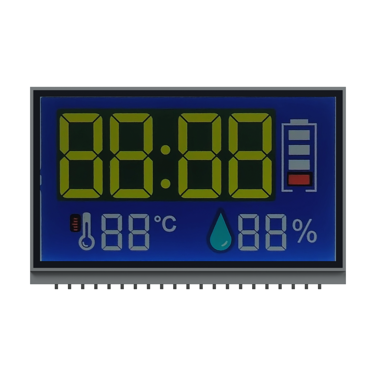
Success LCD begins the review with the drawing and project conditions. Where an input is missing, it should remain an explicit open item until engineering and sourcing agree on the decision owner. For a broader sourcing workflow, use the LCD procurement and RFQ guide.
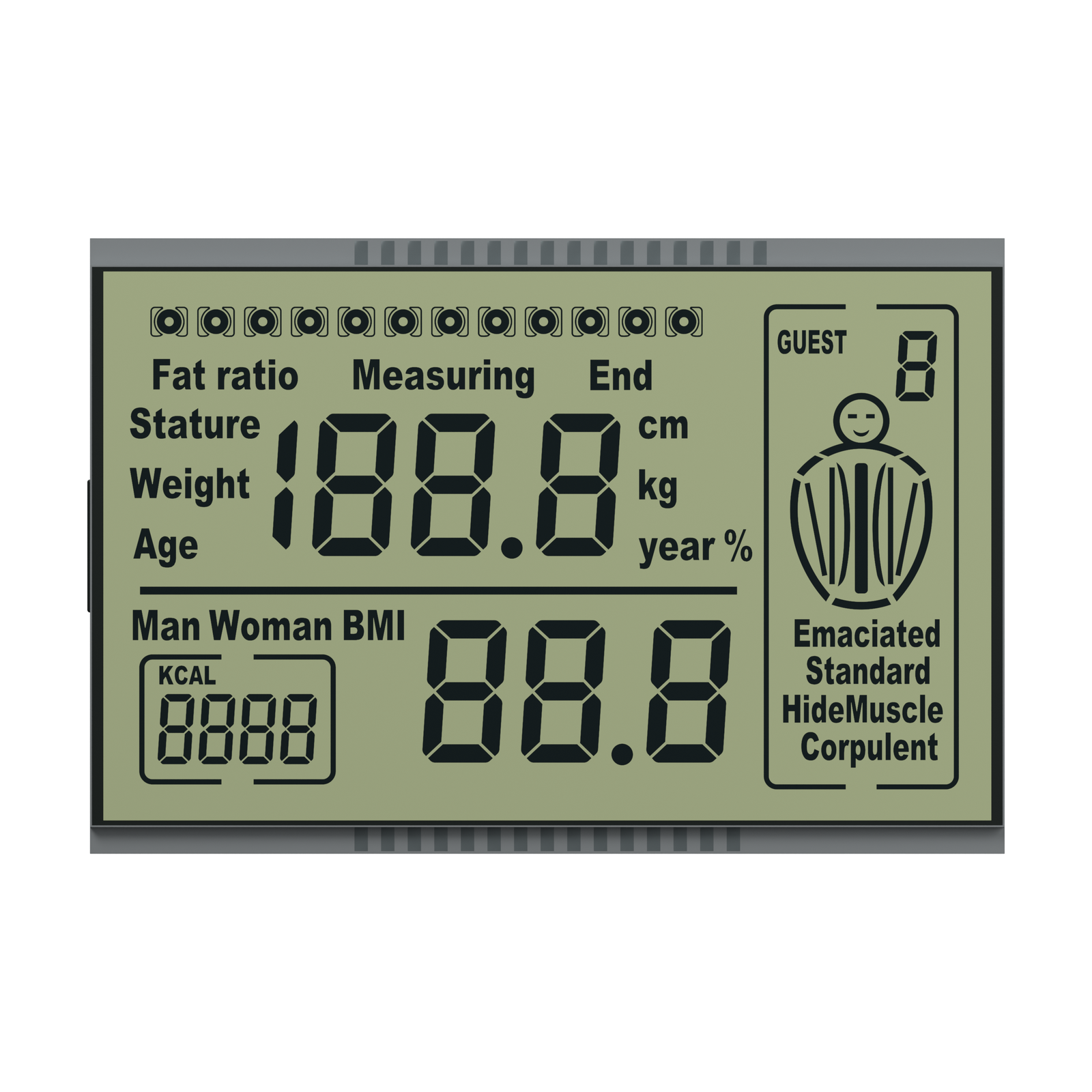
Mono LCD Applications: Map the Display to the Product Risk

Monochrome displays are evaluated for industrial controllers, instruments, meters, medical-equipment interfaces, appliances, handheld products, and vehicle-related panels. Application names do not imply a certification or validated end-use. The OEM must define the relevant regulatory, safety, reliability, and environmental requirements for the finished product.

  • Industrial controls and instruments: prioritize viewing direction, ambient light, temperature, connector retention, vibration context, and lifecycle/change control.
  • Medical equipment interfaces: define readability, failure behavior, cleaning/chemical exposure, traceability, and product-specific regulatory responsibilities.
  • Handheld and low-power products: define sleep states, reflective/transflective use, backlight duty, battery budget, and update behavior.
  • Vehicle-related panels: define temperature, sunlight, viewing direction, illumination uniformity, vibration, lifetime, and qualification requirements. A project must not be described as automotive-qualified without applicable evidence.

What to Send for a Mono LCD or LCM Review

Copy this checklist into your RFQ. If a field is unknown, mark it “open for engineering review” instead of guessing.

  • Application and required display content: segments, icons, characters, resolution, or mixed layout.
  • Glass/module outline, viewing area, thickness, mounting, connector location, and available enclosure/PCB space.
  • Technology or visual preference: TN, HTN, STN, FSTN, VA, positive/negative, and reflective/transflective/transmissive.
  • Viewing direction, ambient-light condition, backlight color/brightness target, and readability criteria.
  • Duty, bias, drive voltage, driver/controller, host interface, pinout, logic level, and power budget.
  • Operating/storage temperature targets and relevant shock, vibration, moisture, chemical, or handling conditions.
  • Drawing, existing datasheet, schematic, photos, samples, or approved artwork where available.
  • Prototype quantity, estimated annual demand, target milestones, lifecycle expectation, and change-control needs.

Send Your Mono LCD/LCM Drawing for Engineering Review

Submit the checklist and available drawing through the RFQ form. After submitting, reply to the confirmation email with drawings or other controlled files if the form does not provide an upload field.

Submit Mono LCD RFQ Requirements

Frequently Asked Questions

What is a monochrome LCD module?

A monochrome LCD module displays information without a full-color image pipeline. It may use fixed segments, character cells, or addressable graphic pixels, and it may include a driver, PCB, connector, or backlight. Selection depends on content, optical mode, electrical drive, construction, environment, and lifecycle requirements.

What is the difference between segment, character, and graphic LCD modules?

A segment LCD uses predefined electrodes for fixed digits and icons. A character module organizes content into repeatable character cells. A graphic module provides addressable pixels for changing text, symbols, or simple diagrams. The right format depends on how much the interface must change after the display is manufactured.

How do TN, HTN, STN, FSTN, and VA LCDs differ?

They are different electro-optical technology families with different design trade-offs. Final appearance and performance also depend on polarizers, viewing mode, drive waveform, backlight, temperature, viewing direction, and cell construction. Compare them against a project specification and validate the selected build rather than choosing by name alone.

What information is needed for a custom Mono LCD quotation?

Provide the content/artwork, dimensions, viewing mode and direction, technology preference, duty, bias, voltage, controller or driver, connector/pinout, backlight, environment, quantity, schedule, and lifecycle needs. Existing drawings, datasheets, schematics, photos, or samples help define the review scope.

What do duty ratio and bias ratio mean in a monochrome LCD?

Duty ratio describes the multiplex relationship between the addressed common lines and the drive cycle. Bias ratio describes the voltage-level division used in the multiplex waveform. Both affect the electrical and optical design and must be coordinated with the glass, driver, voltage, and target appearance.

Can a monochrome LCD module include a backlight?

Yes, a module may include illumination when the selected construction supports it. The RFQ should define color, luminance or readability target, power supply, dimming, thickness, uniformity, operating environment, and duty cycle. The final backlight specification is confirmed for the project rather than assumed from a generic example.

Can an obsolete monochrome LCD module be replaced?

A replacement is possible only after compatibility review. Provide the original drawing or datasheet, sample photos, outline, viewing area, pinout, controller/driver, voltage, interface, optical appearance, environment, and validation criteria. Use the LCD replacement planning guide; do not assume drop-in compatibility.

What are the MOQ and sample lead time for a custom Mono LCD?

MOQ and sample timing depend on the design, tooling, material, construction, validation plan, quantity, and current production review. Send the technical package and demand forecast so the commercial team can quote the applicable scope. This page does not publish a universal MOQ or guaranteed lead time.

Engineering review status: This guide was reviewed under the L-036 publication rules by ENG-001, Senior LCD Engineer. Technical statements are conditional selection guidance. Project capability, performance, compliance, timing, and commercial terms require product-specific evidence and approval.

Technical references: For controller-level definitions and waveform context, see Microchip Technology’s Segment LCD Controller description and Texas Instruments’ Driving Large LCDs With LCD Peripheral of the MSP430. Component documentation illustrates controller capabilities; it does not replace the project LCD drawing or validation plan.

Scroll to Top
Send RFQProducts