
Labels and status artwork
List the required readings, units, languages and status icons. Confirm the segment artwork and COM/SEG allocation for the intended thermostat interface.
Navigate
Rotate, zoom and inspect the product. Loads on request.
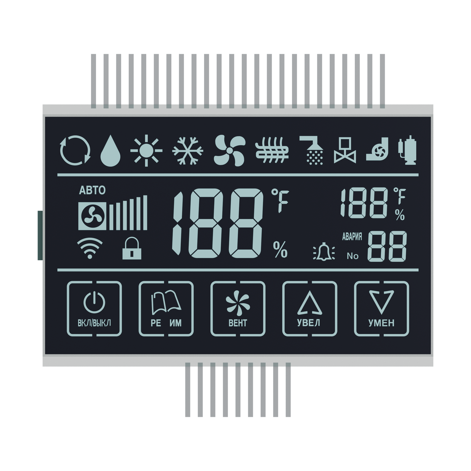
Front visualization of S3999D showing the screen layout and glass outline. Artwork, materials and fine geometry are visual references; final construction is confirmed for the OEM project.
OEM DISPLAY REFERENCE
S3999D is a DFSTN segmented LCD reference for air-conditioning thermostat interfaces. Its negative display mode combines a 76 × 46 mm minimum viewing area with 24 upper pins and 9 lower pins. Review the numeric fields, status icons and labels with your enclosure and LCD driver requirements.
Images, 3D geometry and listed parameters are OEM reference information. Final dimensions, electrical requirements, optical configuration and construction are confirmed for your project.
Short product video. Playback starts when you press play.
01 / REFERENCE CONFIGURATION
A reference configuration for discussing your LCD project. Final specifications are subject to project confirmation.
| Model reference | S3999D |
|---|---|
| Display mode | DFSTN, negative |
| Rear glass width × height | 79.00 ± 0.20 × 53.00 ± 0.20 mm |
| Front glass width × height | 79.00 ± 0.20 × 49.00 ± 0.20 mm |
| Minimum viewing area | 76.00 × 46.00 mm |
| LCD thickness | 2.80 mm maximum |
| Connection | 33 pins: 24 at the top and 9 at the bottom |
| Pin pitch | 2.54 mm |
| LCD operating voltage | 5.0 V |
| Drive condition | 1/4 duty, 1/3 bias |
| Frame frequency | 64 Hz |
| Viewing direction | 12 o’clock |
| Front and rear polarizers | Transmissive, adhesive |
| Operating temperature | −20 °C to +70 °C |
| Storage temperature | −30 °C to +80 °C |
02 / OEM DESIGN
Bring your requirements. We will review the configuration with you.
List the required readings, units, languages and status icons. Confirm the segment artwork and COM/SEG allocation for the intended thermostat interface.
Review the unequal upper and lower pin counts, 2.54 mm pitch and PCB position together. Confirm final pin shape and clearance from the agreed assembly drawing.
Match the LCD driver to the specified multiplex condition and review illumination separately. Confirm appearance under the intended viewing direction and ambient light.
03 / APPLICATION DIRECTION
Use this reference to review an air-conditioning thermostat interface. Its artwork illustrates temperature, humidity and control-status information. The host system supplies sensing, wireless communication and control functions; displayed icons and button outlines do not establish Wi-Fi hardware or touch capability.
04 / PRODUCT SUPPORT
No. They are part of the LCD artwork. Wireless hardware, touch sensing and control functions require separate confirmation for the complete product.
No. The reference has 24 pins at the top and 9 at the bottom, with 2.54 mm pitch. Review both rows and their electrical mapping before laying out the host PCB.
YOUR NEXT LCD PROJECT
Share your required display content, enclosure space, drive arrangement, operating environment and target quantity.


