
Compact panel opening
Check the 30.00 × 24.00 mm minimum viewing area and the 37.00 × 27.00 mm rear glass outline against the remote-control enclosure.
Navigate
Rotate, zoom and inspect the product. Loads on request.
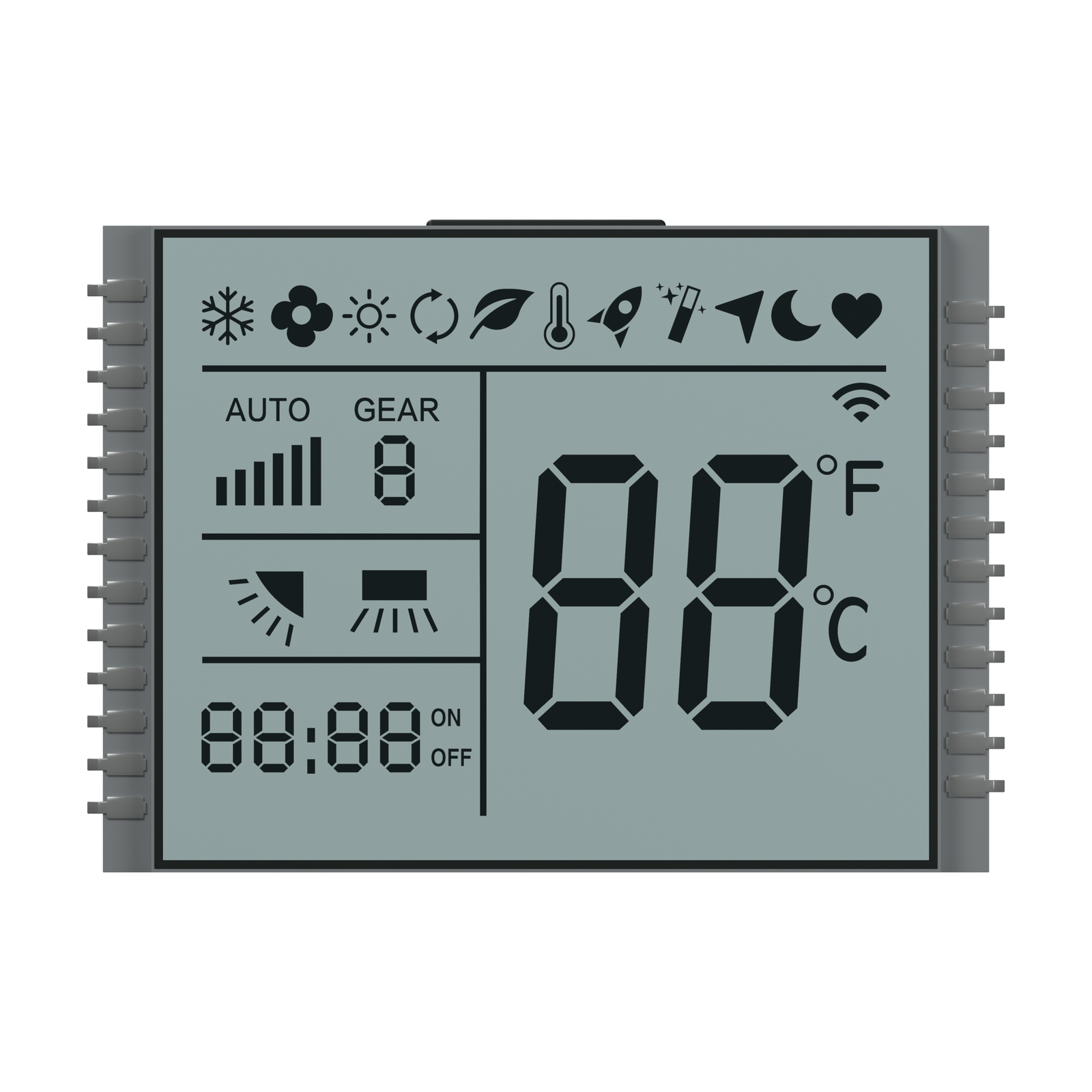
Front rendering of S3498D, showing the display artwork and glass outline. Materials and fine geometry are visual references for the OEM project.
OEM DISPLAY REFERENCE
S3498D is a compact TN, positive-mode segmented LCD reference with a large temperature field, timer digits and mode, fan and airflow symbols. It has a pin row along each side.
Images, 3D geometry and listed parameters are OEM reference information. Final dimensions, electrical requirements, optical configuration and construction are confirmed for your project.
Short product video. Playback starts when you press play.
01 / REFERENCE CONFIGURATION
A reference configuration for discussing your LCD project. Final specifications are subject to project confirmation.
| Model reference | S3498D |
|---|---|
| Display mode | TN, positive |
| Rear glass width × height | 37.00 ± 0.20 × 27.00 ± 0.20 mm |
| Front glass width × height | 33.00 ± 0.20 × 27.00 ± 0.20 mm |
| Minimum viewing area | 30.00 × 24.00 mm |
| LCD thickness | 2.80 mm maximum |
| Glass thickness per layer | 1.10 ± 0.10 mm |
| Pin pitch | 1.80 mm |
| Connection | Pins along both side edges |
| LCD operating voltage | 3.0 V |
| Drive condition | 1/4 duty, 1/3 bias |
| Frame frequency | 64 Hz |
| Viewing direction | 6 o’clock |
| Rear polarizer | Transmissive, adhesive |
| Front polarizer | Transmissive, adhesive |
| Operating temperature | 0 °C to +50 °C |
| Storage temperature | −10 °C to +60 °C |
02 / OEM DESIGN
Bring your requirements. We will review the configuration with you.
Check the 30.00 × 24.00 mm minimum viewing area and the 37.00 × 27.00 mm rear glass outline against the remote-control enclosure.
Review the 1.80 mm pitch and the two side pin rows against the PCB. Confirm the pin assignments and rearward clearance for the assembly.
Both polarizers are listed as transmissive. Review illumination and choose the required temperature, timer and mode symbols for the finished remote.
03 / APPLICATION DIRECTION
Use this reference to plan temperature, timer and operating-mode indications on an air-conditioner remote control. Confirm the required symbols and digit mapping with the remote-control design.
04 / PRODUCT SUPPORT
The reference lists 3.0 V LCD operating voltage, 1/4 duty, 1/3 bias and 64 Hz frame frequency. Check these requirements against your LCD driver; final electrical requirements are confirmed for the project.
The symbols are display artwork. Confirm the required communications, control circuit and segment mapping separately as part of the complete remote-control project.
YOUR NEXT LCD PROJECT
Share your required display content, enclosure space, drive arrangement, operating environment and target quantity.


