
Upper pin row
Allow space for the upper connection row and rearward leads when positioning the PCB and enclosure supports. Confirm pin assignments before routing.
Navigate
Rotate, zoom and inspect the product. Loads on request.
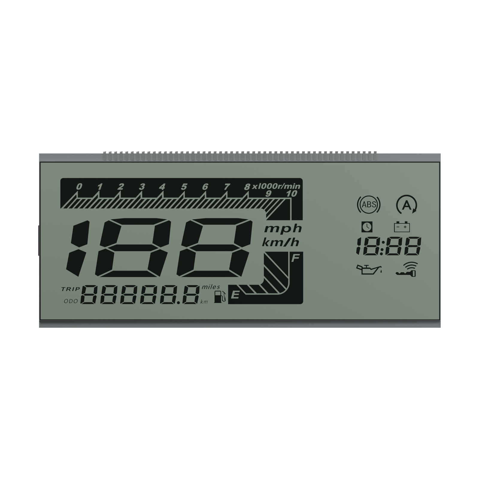
Front rendering of S04778D, showing the screen artwork and glass outline. Materials and fine geometry are visual references for the OEM project.
OEM DISPLAY REFERENCE
S04778D is a wide, positive-mode HTN segmented LCD reference. Its layout combines a prominent speed field with a tachometer scale, odometer fields and status symbols, while the connection row runs along the upper edge.
Images, 3D geometry and listed parameters are OEM reference information. Final dimensions, electrical requirements, optical configuration and construction are confirmed for your project.
Short product video. Playback starts when you press play.
01 / REFERENCE CONFIGURATION
A reference configuration for discussing your LCD project. Final specifications are subject to project confirmation.
| Model reference | S04778D |
|---|---|
| Display mode | HTN, positive |
| Rear glass width × height | 130.90 ± 0.20 × 56.80 ± 0.20 mm |
| Front glass width × height | 130.90 ± 0.20 × 52.10 ± 0.20 mm |
| Minimum viewing area | 127.90 × 49.10 mm |
| LCD thickness | 2.80 mm maximum |
| Glass thickness per layer | 1.10 ± 0.10 mm |
| Connection | 50 pins along the upper edge |
| Pin pitch | 1.80 mm |
| LCD operating voltage | 5.0 V |
| Drive condition | 1/4 duty, 1/3 bias |
| Frame frequency | 64 Hz |
| Viewing direction | 6 o’clock |
| Front and rear polarizers | Transmissive, adhesive |
| Operating temperature | −30 °C to +80 °C |
| Storage temperature | −40 °C to +85 °C |
02 / OEM DESIGN
Bring your requirements. We will review the configuration with you.
Allow space for the upper connection row and rearward leads when positioning the PCB and enclosure supports. Confirm pin assignments before routing.
The reference specifies a 6 o’clock viewing direction. Evaluate contrast and illumination from the intended rider position.
Review the speed digits, scale and status icons against the COM/SEG table and the stated LCD drive condition.
03 / APPLICATION DIRECTION
Assess the speed, distance, fuel and warning information required by a motorcycle instrument. Confirm the complete assembly against the intended viewing position, illumination and vehicle conditions; display symbols do not establish sensors or vehicle approval.
04 / PRODUCT SUPPORT
They are LCD artwork. Vehicle signals, sensors and warning logic are supplied by the host system.
It is the documented LCD operating voltage. Driver circuitry and illumination require their own electrical review.
YOUR NEXT LCD PROJECT
Share your required display content, enclosure space, drive arrangement, operating environment and target quantity.


