
Display layout
Define the readings, symbols and graphics your users need.
Navigate
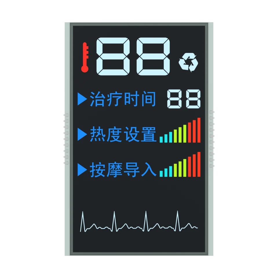
Rotate, zoom and inspect the product. Loads on request.
Product rendering on a white background. Screen artwork, materials and fine details are visual references; final construction is confirmed for the OEM project.
OEM DISPLAY REFERENCE
S1386D is a VA segmented LCD reference for massage device interfaces. Its negative display mode, 56 × 96 mm minimum viewing area and 19 rearward pins provide a starting point for reviewing numeric fields, status indicators and the enclosure layout.
Images, 3D and parameters are reference information. Final dimensions, electrical requirements and construction are confirmed for your project.
See the actual display in operation.
01 / REFERENCE CONFIGURATION
A reference configuration for discussing your LCD project. Final specifications are subject to project confirmation.
| Model reference | S1386D |
|---|---|
| Display mode | VA, negative |
| Rear glass width × height (reference) | 63.00 ± 0.20 × 99.00 ± 0.20 mm |
| Front glass width × height (reference) | 59.00 ± 0.20 × 99.00 ± 0.20 mm |
| Minimum viewing area | 56.00 × 96.00 mm |
| LCD thickness | 2.80 mm maximum |
| Connection | 19 pins: 9 on the left and 10 on the right when viewed from the front |
| Pin pitch | 2.54 mm |
| Pin length (drawing reference) | 10.00 ± 0.50 mm |
| Front and rear polarizers | Transmissive, adhesive |
| LCD operating voltage | 5.0 V |
| Drive condition | 1/4 duty, 1/3 bias |
| Viewing direction | 12 o’clock |
| Operating temperature | 0 °C to +50 °C |
| Storage temperature | −10 °C to +60 °C |
02 / OEM DESIGN
Bring your requirements. We will review the configuration with you.
Define the readings, symbols and graphics your users need.
Define the viewing window, available space, mounting method and connection position.
Confirm your host controller, supply, drive method and backlight requirements before sampling.
03 / APPLICATION DIRECTION
The owner identifies this source model for massage device displays. It provides a reference layout for settings, time and status information. Product safety, control functions and any therapeutic claims require separate evidence for the complete device.
04 / PRODUCT SUPPORT
The current reference uses rearward pins, perpendicular to the rear surface. Viewed from the front, the connection has 9 pins on the left and 10 on the right. Confirm final clearance against the assembly drawing.
The interactive model helps you explore the product form and connection arrangement. It is a visual reference; use the project-confirmed engineering information for assembly design.
YOUR NEXT LCD PROJECT
Share your required display content, enclosure space, drive arrangement, operating environment and target quantity.


