
Display layout
Define the readings, symbols and graphics your users need.
Navigate
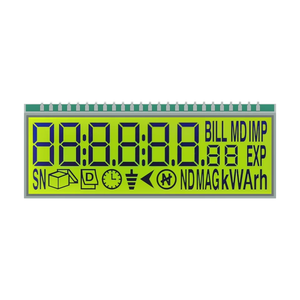
Rotate, zoom and inspect the product. Loads on request.
Product rendering on a white background. Screen artwork, materials and fine details are visual references; final construction is confirmed for the OEM project.
OEM DISPLAY REFERENCE
S2873D is an STN segmented LCD reference for instrumentation. Its yellow-green positive display, 54 × 17 mm minimum viewing area and 25-pin connection support a discussion of numeric readings, unit symbols and status indications in an OEM instrument.
Images, 3D and parameters are reference information. Final dimensions, electrical requirements and construction are confirmed for your project.
See the actual display in operation.
01 / REFERENCE CONFIGURATION
A reference configuration for discussing your LCD project. Final specifications are subject to project confirmation.
| Model reference | S2873D |
|---|---|
| Display type | STN, yellow-green |
| Display / polarizer mode | Positive / transmissive |
| Rear glass width × height | 56.00 ± 0.20 × 21.00 ± 0.20 mm |
| Front glass width × height | 56.00 ± 0.20 × 19.00 ± 0.20 mm |
| Minimum viewing area | 54.00 × 17.00 mm |
| Connection | 25 pins, 2.00 mm pitch |
| Rearward pin reach (drawing reference) | 7.00 ± 0.50 mm |
| LCD operating voltage | 2.8 V |
| Drive condition | 1/4 duty, 1/3 bias; 64 Hz |
| Viewing direction | 6 o’clock |
| Operating temperature | −20 °C to +80 °C |
| Storage temperature | −30 °C to +90 °C |
02 / OEM DESIGN
Bring your requirements. We will review the configuration with you.
Define the readings, symbols and graphics your users need.
Define the viewing window, available space, mounting method and connection position.
Confirm your host controller, supply, drive method and backlight requirements before sampling.
03 / APPLICATION DIRECTION
The source model is identified for instrumentation. Use its segmented layout as a reference for measured values and status information. Displayed unit or tariff symbols describe the artwork and do not establish the accuracy, metering functions or certification of a finished instrument.
04 / PRODUCT SUPPORT
It identifies the reference physical connection, with 2.00 mm pitch. Confirm the COM/SEG allocation and LCD drive requirements against the agreed project pin map.
The interactive model helps you explore the product form and connection arrangement. It is a visual reference; use the project-confirmed engineering information for assembly design.
YOUR NEXT LCD PROJECT
Share your required display content, enclosure space, drive arrangement, operating environment and target quantity.


