
Segment LCD Duty And Bias Explained: Multiplexing, Voltage And Frame Frequency
Quick answer: on a segment LCD, duty tells you how many common electrodes (COMs) share the segment lines. A 1/4 duty display has 4 COMs, and each COM is selected for one quarter of every frame. Bias tells you how many voltage levels the driver uses: 1/3 bias divides the LCD drive voltage into steps of one third. The best bias for N commons is about 1/(√N + 1), which is why 1/4 duty goes with 1/3 bias, 1/8 duty with 1/4 bias and 1/16 duty with 1/5 bias.
The glass is designed for one drive condition. In the SuccessLCD segment LCD catalogue the most common condition is 1/4 duty, 1/3 bias at 64 Hz, with LCD operating voltages between 2.7 V and 5.5 V, and the controller must be set to the same duty, bias and voltage for full contrast without ghosting.
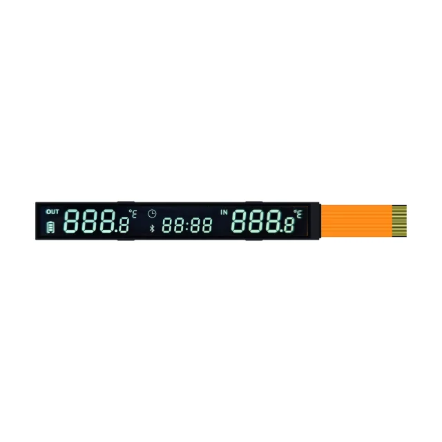
COM And SEG: How A Segment LCD Is Wired
Every segment, icon or decimal point is the overlap of one segment electrode (SEG) on one glass plate and one common electrode (COM, also called the backplane) on the other. A segment turns on when the RMS voltage between its SEG and COM is above the liquid crystal’s threshold, and stays off when it is below.
- Static drive (1 COM): every segment has its own SEG pin and they all share a single COM. Off segments see no voltage at all, so contrast and viewing angle are the best possible, but the pin count equals the segment count plus one.
- Multiplexed drive (N COMs): the segments are divided into N groups. Each SEG line serves N segments, one on each COM, and the driver selects the COMs one after another. This is what “duty” describes.
Pins needed = COM count + SEG count
| Drive | COM | SEG | Segments with 32 pins |
|---|---|---|---|
| Static | 1 | 31 | 31 |
| 1/2 duty | 2 | 30 | 60 |
| 1/4 duty | 4 | 28 | 112 |
| 1/8 duty | 8 | 24 | 192 |
Multiplexing is what lets a thermostat, meter or tire-pressure display show dozens of digits and icons from a small microcontroller. The price is contrast margin, explained below.
What 1/4 Duty, 1/8 Duty And 1/16 Duty Mean
Duty is the fraction of each frame for which one COM is selected. With 1/4 duty the driver cycles through COM0 to COM3, so each row of segments is addressed for 25 % of the frame. With 1/8 duty each COM gets 12.5 %, and so on. Because the liquid crystal responds to the RMS voltage over the whole frame, the more COMs there are, the smaller the difference between an “on” and an “off” segment becomes.
Segment displays usually run from static to 1/8 duty. Character and graphic modules use much higher duties: the SuccessLCD 20 × 4 character glass S4132D runs at 1/16 duty, and our dot-matrix chip-on-glass references run at 1/33 and 1/64 duty. Those displays need liquid crystal modes with a steeper electro-optical curve, such as STN and FSTN; see monochrome LCD types.
What Bias Means, And Why 1/4 Duty Uses 1/3 Bias
In a multiplexed display the driver applies a set of intermediate voltage levels so that unselected segments see only a small voltage. With 1/3 bias the levels are 0, V/3, 2V/3 and V, where V is the LCD operating voltage. A selected “on” segment sees the full V during its COM time and V/3 for the rest of the frame; an “off” segment never sees more than V/3.
The bias that gives the largest on/off difference for N commons was derived by Alt and Pleshko:
Maximum Von(rms) / Voff(rms) = √[(√N + 1) / (√N − 1)]
| Duty (N) | Optimum bias | Bias used in practice | Max Von / Voff | SuccessLCD catalogue example |
|---|---|---|---|---|
| Static (1) | — | — | Off segments see 0 V | S3960D four-digit HTN, static drive |
| 1/2 | 1/2.4 | 1/2 | 2.41 | S3686D wide TN alphanumeric, 1/2 duty, 1/2 bias |
| 1/3 | 1/2.7 | 1/3 | 1.93 | S3299D FSTN, 1/3 duty, 1/3 bias |
| 1/4 | 1/3 | 1/3 | 1.73 | S3423D TN water-meter display, 1/4 duty, 1/3 bias |
| 1/8 | 1/3.8 | 1/4 | 1.45 | S3438D DFSTN tire-pressure display, 1/8 duty, 1/4 bias |
| 1/16 | 1/5 | 1/5 | 1.29 | S4132D 20 × 4 STN character glass, 1/16 duty, 1/5 bias |
| 1/32 – 1/33 | 1/6.7 | 1/7 | 1.20 | S3092D segment COG (1/32) and S4417D dot-matrix COG (1/33), 1/7 bias |
| 1/64 | 1/9 | 1/9 | 1.13 | S2983D dot-matrix COG FSTN, 1/64 duty, 1/9 bias |
Every pairing in the catalogue follows the 1/(√N + 1) rule. The last column shows the trade-off: at 1/4 duty an “on” segment receives at most 1.73 times the RMS voltage of an “off” segment, while at 1/64 duty the ratio falls to 1.13. That is why high-duty displays need STN or FSTN liquid crystal, careful voltage setting and often temperature compensation.
Can 1/4 Duty Use 1/2 Bias?
Yes, and some drivers support only 1/2 bias. The on/off ratio at 1/4 duty drops from 1.73 with 1/3 bias to about 1.53 with 1/2 bias, so the glass and voltage must be designed for it. The SuccessLCD HTN reference S3980D is specified at 1/4 duty, 1/2 bias, 3.0 V. Never switch an existing display from 1/3 to 1/2 bias without retesting contrast and ghosting.
LCD Operating Voltage And Temperature
The LCD operating voltage (often written VLCD or VOP) is set by the threshold voltage of the liquid crystal mixture together with the duty and bias. Too low, and “on” segments look faint. Too high, and “off” segments start to appear: the faint shadow known as ghosting or crosstalk.
- In the SuccessLCD catalogue, segment references are specified at 2.7 V to 5.5 V, most often 3.0 V, 3.3 V or 5.0 V, so the glass can match a 3 V battery product or a 5 V supply.
- The threshold voltage falls as temperature rises and increases in the cold. A display that is set correctly at room temperature can ghost when hot and fade when cold. Products with a wide operating range use a driver with temperature compensation or a contrast adjustment.
- Response time also slows in the cold; see LCD response time at low temperature.
Why Segment LCDs Must Be Driven With AC
A liquid crystal cell must see no net DC voltage. A DC component slowly drives ions through the liquid crystal and degrades the alignment layers, which leads to fading, residual images and permanent damage. LCD drivers therefore reverse the polarity of the drive waveform every frame (or every line), so the average voltage across each segment is zero.
If you drive glass directly from microcontroller GPIO pins, you must generate this AC waveform in firmware, including the intermediate bias levels for multiplexed glass. Microcontrollers with a built-in LCD controller, or a dedicated segment driver such as an HT1621-class 32 × 4 driver, handle this automatically.
Frame Frequency
The frame frequency is how often the whole display is refreshed. Most SuccessLCD segment references are specified at 64 Hz; a few use 75 Hz or 128 Hz. Too low a frame rate causes visible flicker, especially with multiplexed glass. Too high a frame rate increases power consumption and can reduce contrast because the cell has less time to respond. Use the frame frequency on the drawing unless the display has been tested at another value.
How To Choose Duty And Bias For A New Display
- Count the segments. Include every digit segment, decimal point, colon, unit legend and icon.
- Check the controller. Note how many COM and SEG outputs your microcontroller or driver IC has, and which duty and bias settings it supports.
- Use the lowest duty that fits. Lower duty gives more contrast, a wider viewing angle and more tolerance to temperature. Move to 1/8 duty only when 1/4 duty would need too many pins.
- Match the glass to the driver. Duty, bias, VLCD and frame frequency are design inputs for the glass and its liquid crystal mode; agree them before the artwork is finalised.
- Test at the temperature extremes. Check for ghosting when hot and faint segments when cold, at the viewing direction used in the product.
When SuccessLCD designs a custom segment LCD, the COM/SEG allocation, pin map and drive condition are drawn up together with the artwork, so that the glass works with the driver already chosen for the product. For digit and icon layout, see 7-segment, 14-segment and 16-segment LCD digits.
Troubleshooting Contrast Problems
| Symptom | Likely cause | What to check |
|---|---|---|
| Off segments faintly visible (ghosting; on a module with a V0 pin, see contrast adjustment) | VLCD too high, wrong bias, or high temperature | Measure VLCD; confirm duty and bias registers match the drawing |
| On segments faint | VLCD too low, low temperature, or wrong duty | Measure at the glass, not only at the driver supply |
| Visible flicker | Frame frequency too low | Set the frame frequency on the drawing, typically 64 Hz in our catalogue |
| One row of segments wrong | COM mapping or a bad contact | Check the pin map and the connection; see LCD connection types |
| Gradual fading or stuck image | DC component on the glass | Confirm the waveform is AC with no DC offset |
Duty And Bias FAQs
What does 1/4 duty, 1/3 bias mean on an LCD datasheet?
It means the display has 4 common electrodes that are selected one after another, each for a quarter of every frame, and the driver uses voltage levels in steps of one third of the LCD operating voltage. It is the most common drive condition for segment LCDs.
How many segments can a 1/4 duty LCD drive?
Four times the number of segment lines. For example, 4 COM pins and 28 SEG pins give up to 112 segments from 32 pins, compared with 31 segments for the same pin count with static drive.
What is the correct bias for a given duty?
The optimum bias is about 1/(√N + 1), where N is the number of commons: 1/3 bias for 1/4 duty, 1/4 bias for 1/8 duty, 1/5 bias for 1/16 duty and 1/9 bias for 1/64 duty.
What happens if an LCD is driven at the wrong duty or bias?
Contrast drops and off segments may become visible as ghosting, or on segments may look faint. The glass is designed for one drive condition, so the controller should be set to the duty, bias, voltage and frame frequency on the drawing.
Is static drive better than multiplexed drive?
Static drive gives the best contrast and widest viewing angle because off segments see no voltage, but it needs one pin per segment. Multiplexed drive is used when the display has too many segments for the available pins.
Why must an LCD be driven with AC?
A net DC voltage across a liquid crystal cell causes electrochemical degradation, leading to fading, residual images and permanent damage. LCD drivers reverse the drive polarity every frame so the average voltage is zero.
Designing a segment LCD around a specific controller? Send the segment list, the driver or microcontroller, supply voltage and operating temperature. Send your display requirements for an engineering review, or browse monochrome LCD references. For a new segment design, see custom LCD display projects.