
LCD Smearing in the Cold: What a −20°C Rating Leaves Out
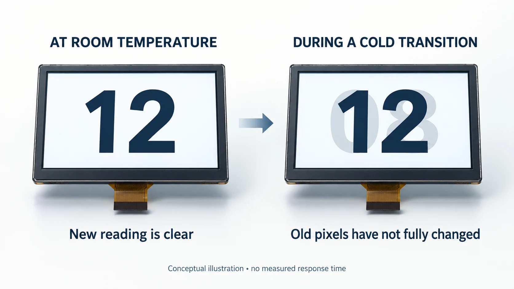
An outdoor control panel powers up. The backlight is on, the menu appears, and the temperature is within the LCD’s stated operating range. Then a reading changes from 08 to 12—and traces of the old digits remain long enough to make the new value hard to read.
That is a different problem from a screen that will not start. It also exposes a gap in a common purchasing requirement: “The LCD must operate at −20°C.”
An operating-temperature rating alone does not establish how quickly a cold LCD will show a clear new image. For a display that carries changing readings, you need two acceptance limits: time to the first usable screen, and time to a readable update after the screen is already running.
On this page
The response-time number may belong to a different temperature
A useful example appears in Kyocera’s TCG062HVLDA-G20 specification, revised in January 2026. Its environmental absolute-maximum table lists an operating range of −20 to +70°C. A separate optical table specifies response at an ambient temperature of 25°C:
| Specification field | Published condition or value |
|---|---|
| Operating temperature | −20 to +70°C, under environmental absolute maximum ratings |
| Optical measurement temperature | 25°C ambient |
| Rise / down response time | 15 ms / 20 ms typical, at the optical test conditions |
The temperature-table note explicitly separates operation from the optical characteristics specified at 25°C. These response figures therefore do not establish the module’s switching speed at −20°C. They are also typical values, not maximum limits. See the Kyocera specification, printed pages 2 and 4.
This is a third-party example of how to read a specification, not a SuccessLCD product claim. When comparing wide-temperature TFT LCD modules, ask for the response conditions as well as the operating range.
Do the same with a reliability report. Check whether optical performance was assessed while the display was cold or only after it returned to room temperature. A post-exposure inspection cannot, by itself, answer how clearly changing numbers appeared during the cold period.
Why the old image can take longer to disappear
Liquid-crystal switching involves physical reorientation of the material. As temperature falls, increased viscosity can slow that process; Microchip’s LCD fundamentals note, pages 11–12, describes the effect. Material choice and display construction matter. Rao, Gauza and Wu’s research examines the temperature dependence of rotational viscosity and elastic constants in two commercial mixtures. Ask for response data at the required cold condition rather than applying a universal conversion factor.
The effect can be easy to miss on a static startup logo. Leave the same image on screen and it may eventually look acceptable. Change numbers, scroll a list or switch a gray button between states, and slow transitions become more apparent. Here, “smearing” means pixels have not yet completed a change; it does not by itself establish permanent damage or long-term image retention.
Also keep the host separate from the panel. A 60 Hz input delivers a new frame about every 16.7 ms; that arithmetic says nothing about how long the pixels take to reach the new optical state. If the host sends the new value late, changing the LCD will not remove that part of the delay.
Confirm that the display input contains the intended new image before attributing the residual digits to the LCD.
If no valid image appears at all, start with the LCD power-on and white-screen checks. A missing frame and a slowly settling frame need different evidence.
Measure two delays, not just “the display came on”
For sample approval, separate these two questions:
| Acceptance item | Start event | Finish event |
|---|---|---|
| First usable screen | Product power is applied | The required startup information meets the agreed readability criteria |
| Readable update | A defined data change enters the display path | The new reading meets those criteria and the previous state no longer causes ambiguity |
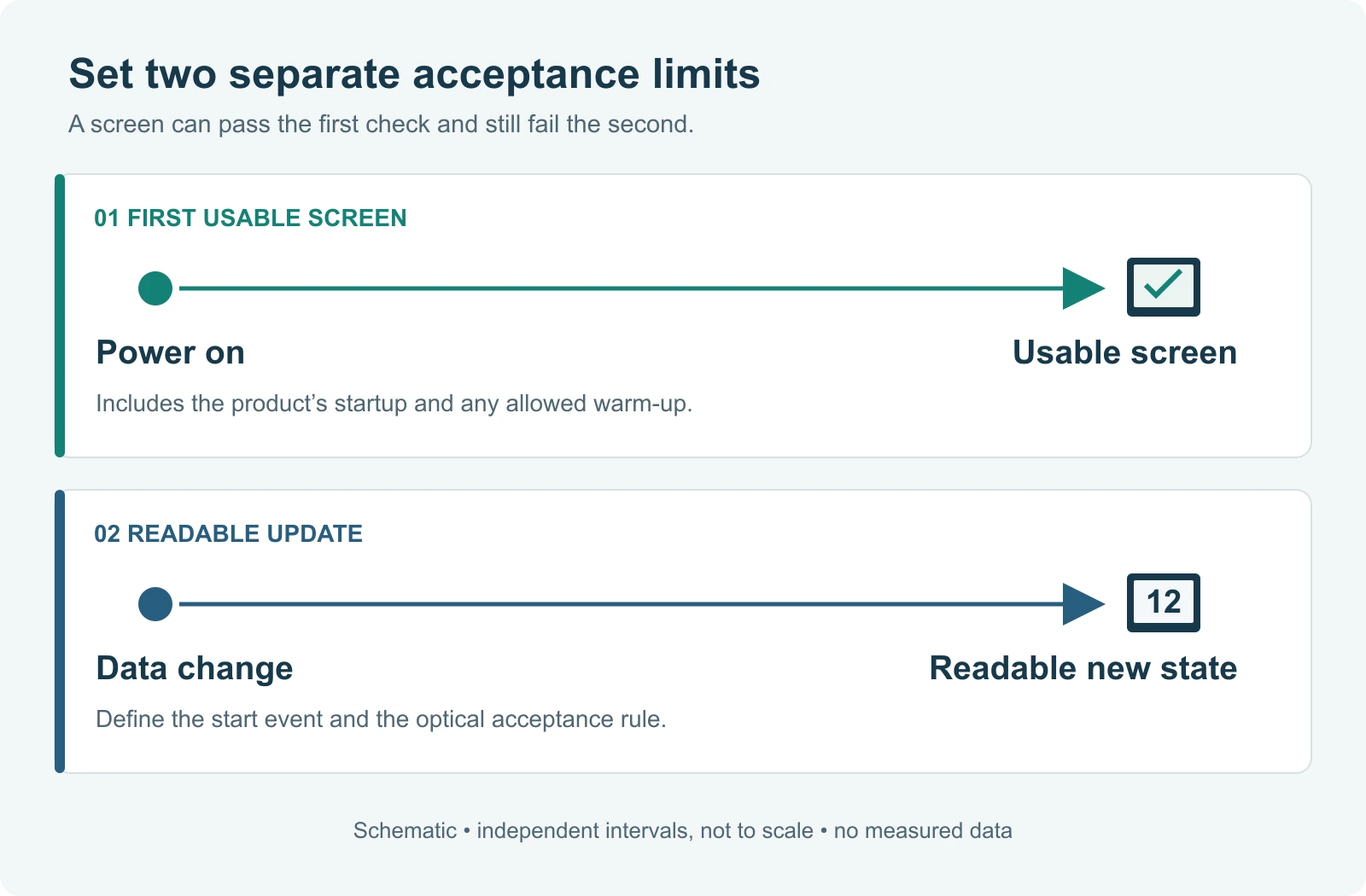
The second interval is an end-to-end system requirement if its timer starts in the application. It includes software and transport delays as well as the panel’s optical transition. To isolate panel response, the supplier needs an agreed display-input reference, optical measurement method and transition definition. Do not label a software-to-screen measurement as datasheet Tr or Tf.
A heater adds another condition. R. STAHL’s ET-498-2FX panel-PC datasheet, for example, distinguishes heater-equipped operation and warns that cold starts can require warm-up before the display becomes legible. That is a condition of that complete product, not a warm-up allowance to copy into every LCD project. See R. STAHL, Ambient Conditions, page 4.
If your equipment must show a readable value immediately, a test performed after heating has stabilized cannot answer that requirement.
Make the cold test resemble the job
The following is a proposed sample test, not a qualification standard. Agree the conditions and limits with the supplier before testing.
Start with the assembled product, powered off. Include the intended host, display, enclosure, cover stack and heater configuration. Establish the cold condition using an agreed stabilization criterion and temperature measurement locations. A chamber-air reading alone does not prove that the panel and electronics have reached the same temperature. Record whether standby power or heating remains active; those conditions change what “cold start” means.
Keep the test within the approved electrical, temperature and humidity conditions for the assembly, including any non-condensation requirement.
Capture the first start before allowing a warm-up run. Log power-on, the first valid display input where accessible, and the first usable screen. Keep the expected backlight setting, supply conditions, viewing position and ambient illumination in the record. If heating is present, log its state and the temperature at the agreed panel measurement point.
Then exercise a specific state change. Use the actual font, size and colors of a critical reading. For example, alternate 08 and 12 so that some pixels turn on while others turn off. Test both directions. Include the gray or color transitions the real interface uses; a black-to-white response number does not automatically describe every transition.
Hold each state long enough to inspect settling, then repeat at the application’s real update cadence. A display that looks clear after a long pause may still blur consecutive updates.
Record performance while cold and as the assembly warms. Repeat the same content and measurement method at the room-temperature reference condition. Keep these records separate. The comparison is useful for diagnosis, but the pass/fail decision still belongs to the actual operating requirement.
A video is useful evidence of a visible problem. For a response limit in milliseconds, however, agree a measurement method with enough timing resolution and account for the camera’s exposure and sampling. A few video frames are not automatically a calibrated optical-response measurement.
Put a readable state into the purchase requirement
“No obvious ghosting” is difficult to enforce unless both sides know what “obvious” means. Before samples arrive, define:
- The cold condition: temperature reference, measurement locations, stabilization criterion, and power or heater state before startup.
- The two time limits: maximum power-on-to-usable-screen time and maximum data-change-to-readable-update time.
- The content and viewing conditions: exact test screens, transition directions, update cadence, viewing position, illumination and backlight setting.
- The optical acceptance rule: for instrumented work, the agreed luminance thresholds, measurement area and permitted residual signal; for a task-level check, a documented readability procedure and approved reference images.
- The evidence: sample and hardware revisions, firmware, temperature logs, timing records and the number of samples and repeats agreed for approval.
Here are two lines to adapt for the purchase brief. Fill in the time limits from the application requirement and attach the agreed test conditions:
Cold start: At the specified stabilized cold condition and heater/standby configuration, screen A must meet the attached readability criteria within _____ seconds of product power-on.
Update: Under the defined operating condition, A → B and B → A must each meet those criteria within _____ (ms or s) of the named application/input event, at an update interval of _____ (ms or s).
Keep those as separate lines in the LCD module RFQ, then carry them into the sample-validation checklist. Do not let a successful power-on tick both boxes.
The useful question for a supplier is specific: “At our minimum operating condition, when the value changes from 08 to 12, how soon will 12 be unambiguous—and what test demonstrates it?” Send the two screen images with the request. They explain the problem more precisely than an operating-temperature range alone.