
FPC Vs FFC: LCD Connection Types Explained
Quick answer: an FFC (flat flexible cable) is a standard ribbon of parallel flat copper conductors laminated between insulating films, used as a jumper between two connectors. An FPC (flexible printed circuit) is a custom circuit etched on a flexible film, so it can have any outline, bends, multiple layers, stiffeners and even components. On an LCD module, the tail that leaves the glass is almost always an FPC; an FFC is typically used to extend that connection across the product to the main board.
SuccessLCD uses five main ways to connect LCD glass to a host board: metal pins, FPC, zebra (elastomeric) connectors, heat-seal connectors and chip-on-glass with an FPC. The right choice depends on the board layout, enclosure pressure, assembly method and how many signals must leave the glass.
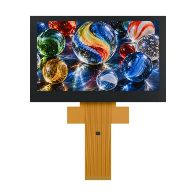
FPC Vs FFC Compared
| Point | FFC (flat flexible cable) | FPC (flexible printed circuit) |
|---|---|---|
| Construction | Parallel flat copper conductors laminated between insulating films | Copper traces patterned on a flexible film, usually polyimide, with a cover layer |
| Shape | Straight strip with conductors at a fixed, uniform pitch | Any outline: necks, branches, bends, widened areas and test pads |
| Layers and parts | Single conductor layer, no components | One or more layers; can carry components, shielding and stiffeners |
| Typical role in a display design | Board-to-board or board-to-module jumper | The module’s own tail bonded to the glass, or a custom touch-panel tail |
| Design effort | Often a catalogue part chosen by pitch, conductor count, length and contact side | Designed for the project; outline, pinout and stiffener follow the module drawing |
| Best when | A simple, straight connection between two standard connectors is enough | The connection must fit a tight space, route around parts or join directly to LCD glass |
Both end in exposed contacts that mate with a board connector, often a ZIF (zero insertion force) or LIF (low insertion force) type. That is why the two are easy to confuse: from the connector’s point of view they can look alike, but an FPC is a designed circuit while an FFC is a cable.
Where FPC And FFC Appear On An LCD Module
- Module tail (FPC). On TFT modules and chip-on-glass LCDs, an FPC is bonded to the contact ledge of the glass, usually with anisotropic conductive film, and carries the display interface, power and backlight lines to the host connector.
- Touch panel tail (FPC). A touch panel usually has its own FPC. For example, the S35001D 3.5-inch TFT uses a 54-pin LCD FPC plus a separate 10-pin touch FPC.
- Extension (FFC). When the display sits far from the main board, an FFC can bridge the gap between a board connector and an adapter or the module connector. Check that the conductor count, pitch and contact side match at both ends.
Because the module FPC is part of the display design, its pinout is fixed by the module drawing. Two modules with the same size and resolution can still have different FPC outlines and pin assignments, which is a common cause of replacement problems. See LCD FPC connector mismatch on replacement displays.
Other LCD Connection Types: Pins, Zebra, Heat Seal And COG
| Method | How it works | Typical fit | Watch for |
|---|---|---|---|
| Metal pins | Pins clipped onto the glass contact edge and soldered into the PCB | Segment LCDs on through-hole boards; robust mechanical retention | Pin pitch, row spacing and the height between glass and board |
| FPC | Flexible circuit bonded to the glass, ending in connector contacts or solder pads | Thin products, displays away from the board, TFT and COG modules | Bend radius, stiffener, contact side and connector locking |
| Zebra (elastomeric) connector | A strip of alternating conductive and insulating silicone layers pressed between glass contacts and PCB pads | Compact handheld instruments and thermometers; no soldering to the glass | Needs a frame or bezel that applies even, lasting compression |
| Heat seal | A thin flexible film with printed conductors bonded to the glass and board with heat and pressure | Very thin, low-profile segment designs such as scales | Bonding process control and how the film is routed |
| Chip-on-glass (COG) + FPC | The driver IC is mounted on the glass, so the FPC carries a short interface instead of every segment line | Dot-matrix and high-segment-count displays; fewer host pins | Interface type, driver commands and ESD protection on the FPC lines |
For segment and character displays, the connection is often chosen together with the driver: direct-drive segment glass needs one line per segment or common, while COG LCDs move the driver onto the glass and reduce the connection to a serial or parallel bus.
How To Match An FPC Or FFC To Its Connector
- Pitch and contact count. Both must match the connector exactly; a near match will not seat correctly.
- Contact side. Confirm whether the connector contacts the top or bottom of the tail, and whether pin 1 ends up on the correct side after the tail is bent.
- Tail thickness at the contact area. ZIF connectors specify the total thickness, including any stiffener, that they accept.
- Locking style. Flip-lock, slide-lock or friction types need different tail ends and assembly steps.
- Length and bend. Keep bends away from the bonded glass area and the stiffener edge, and check the bend radius in the drawing.
- Current-carrying lines. Backlight anode and cathode lines carry more current than signal lines; confirm how many contacts are assigned to them.
A module drawing review catches most of these issues before samples are built; see the LCD module drawing and specification review checklist.
Video: LCD Connection Types On Real Parts
This one-minute SuccessLCD explainer shows metal pins, an FPC tail, a zebra connector, a heat-seal film and a chip-on-glass LCD with FPC on real catalogue parts, then the checks to make before you freeze the PCB.
SuccessLCD Catalogue Examples
| Reference | Display | Connection |
|---|---|---|
| S04773D | HTN segment LCD for temperature controllers | 32 pins in two rows of 16, 2.54 mm pitch |
| S1386D | VA negative-mode segment LCD for massage devices | 19 pins: 9 on the left and 10 on the right, viewed from the front |
| S2238D | Compact VA negative-mode segment LCD | FPC with 23 contacts |
| S4264D | Compact HTN segment LCD for golf rangefinders | FPC with 32 contacts |
| S4132D | STN 20 × 4 character LCD glass | ITO contact areas for a zebra connector |
| S3983D | HTN food thermometer LCD | Zebra connector on flat glass contacts |
| S3689D | TN body fat scale LCD | Heat seal: 31 glass contacts, 16 on one edge and 15 on the opposite edge |
| S2947D | Segment COG LCD for electric-assist bicycle displays | Chip-on-glass with FPC and backlight |
| S35001D | 3.5-inch, 320 × 240 RGB TFT with capacitive touch | 54-pin LCD FPC plus 10-pin touch FPC |
Connection method, pin assignment and tail geometry are confirmed on the drawing for each project. Browse monochrome LCD modules and TFT LCD modules for more references.
FPC, FFC And LCD Connection FAQs
What is the difference between FPC and FFC?
An FFC is a standard flat cable of parallel copper conductors laminated in insulating film, used as a jumper between connectors. An FPC is a custom flexible printed circuit that can have any outline, several layers, stiffeners and components. LCD module tails are normally FPCs; FFCs are used to extend connections between boards.
Can I replace an FPC with an FFC?
Only where the FPC is simply acting as a straight jumper and the FFC matches the pitch, contact count, contact side and thickness required by both connectors. An FPC that is bonded to LCD glass cannot be replaced by an FFC; it is part of the display module.
What is a zebra connector on an LCD?
A zebra connector is an elastomeric strip with alternating conductive and insulating layers. It is compressed between the contact pads on the LCD glass and the pads on the PCB, so each pad connects through the conductive layers without soldering. The enclosure or a frame must hold steady pressure on it.
Which LCD connection method is the most robust?
It depends on the product. Soldered metal pins give strong mechanical retention on through-hole boards, FPCs suit thin products and remote mounting, and zebra connectors avoid soldering but rely on lasting compression. The choice should be validated with vibration, drop and temperature testing in the finished enclosure.
Why do two LCDs with the same size have different connectors?
The connector follows the module design, not the display size. Driver choice, interface, backlight wiring and the manufacturer’s FPC layout all change the pin count, pitch and pin order, so a replacement module needs its drawing checked against the host connector.
Need a display connection reviewed? Send your PCB connector, enclosure space, assembly method and the signals the display needs. See what an LCD module is, what to include in a TFT LCD module RFQ or send your display requirements for an engineering review. For a custom FPC, see custom TFT display engineering.