
Tall display window
Check the viewing window, row spacing and legibility in the proposed housing orientation.
Navigate
Rotate, zoom and inspect the product. Loads on request.
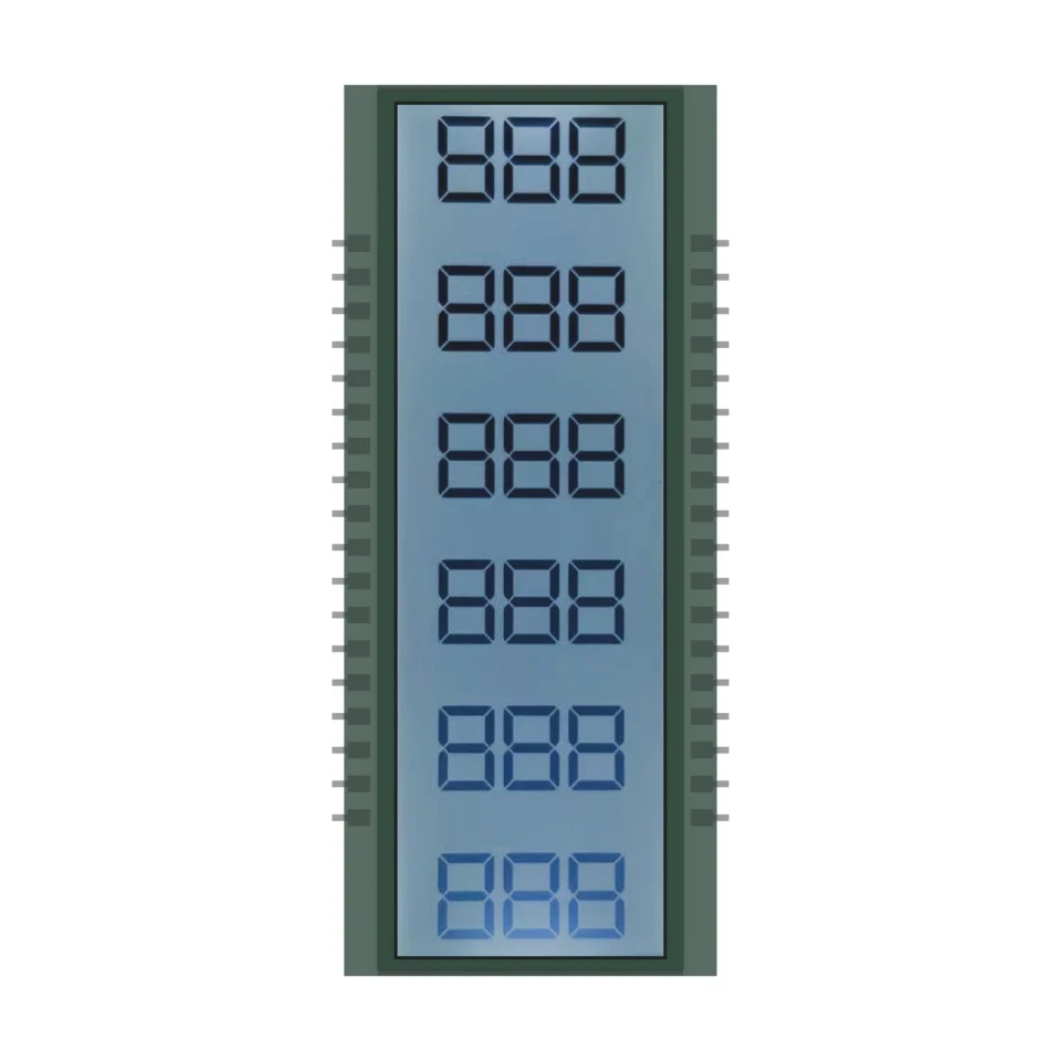
Front rendering of S3396D, showing the display artwork and glass outline. Materials and fine geometry are visual references for the OEM project.
OEM DISPLAY REFERENCE
S3396D arranges six three-digit fields vertically in a narrow glass outline. Connections along both sides leave the central area available for stacked readings.
Images, 3D geometry and listed parameters are OEM reference information. Final dimensions, electrical requirements, optical configuration and construction are confirmed for your project.
Short product video. Playback starts when you press play.
01 / REFERENCE CONFIGURATION
A reference configuration for discussing your LCD project. Final specifications are subject to project confirmation.
| Model reference | S3396D |
|---|---|
| Glass outline | 28.03 ± 0.20 × 67.00 ± 0.20 mm |
| Minimum viewing area | 20.00 × 64.00 mm |
| Maximum LCD thickness | 2.80 mm max |
| Display mode | HTN, positive |
| Connection | Pins |
| LCD operating voltage | 3.3 V |
| Drive condition | 1/4 duty, 1/3 bias |
| Frame frequency | 64 Hz |
| Viewing direction | 6 o'clock |
| Rear polarizer | Transmissive, adhesive |
| Front polarizer | Transmissive, adhesive |
| Operating temperature | −20 to +70 °C |
| Storage temperature | −30 to +80 °C |
02 / OEM DESIGN
Bring your requirements. We will review the configuration with you.
Check the viewing window, row spacing and legibility in the proposed housing orientation.
Allow space for connections on both sides and confirm the contact assignment and rear lead geometry with the project PCB.
Confirm your host controller, supply, drive method and backlight requirements before sampling.
03 / APPLICATION DIRECTION
The source application is laser-ranging equipment. This is a display reference; it does not include a laser source, detector or ranging electronics and does not specify measurement performance.
ENGINEERING NOTES
How S3396D relates to LCD mode, drive, connection and integration choices, with links to the SuccessLCD engineering guides.
High twisted nematic glass: better contrast and a wider viewing angle than TN at a similar cost. Compare TN, HTN, STN, FSTN, DFSTN and VA →
4 common electrodes share the segment lines. Set the controller to the duty, bias, voltage and frame frequency on the drawing. Duty and bias explained →
Metal pins are soldered into the PCB, the most robust connection for segment glass. LCD connection types →
Digit, decimal point and icon layout set the segment count and pin map. 7-segment digit design →
04 / PRODUCT SUPPORT
The reference lists 3.3 V LCD operating voltage and 1/4 duty, 1/3 bias, at 64 Hz frame frequency. Check these requirements against your LCD driver; final electrical requirements are confirmed for the project.
No. This reference covers the LCD display. The laser, detector, measurement electronics and performance requirements are separate parts of the finished system.
YOUR NEXT LCD PROJECT
Share your required display content, enclosure space, drive arrangement, operating environment and target quantity.


