
Display layout
Share the digits, symbols, icons or graphics needed for your LED mirror interface.
Navigate
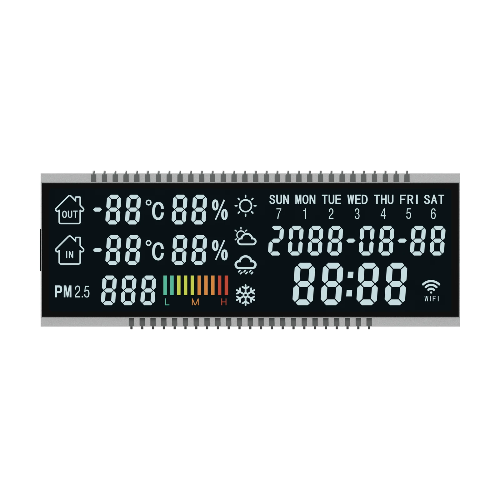
Six rendered views of S2701D. Select a thumbnail to switch views.
Front visualization of S2701D, an LCD reference design for LED mirrors. The generated image illustrates product appearance; final construction is defined for the OEM project.
OEM DISPLAY REFERENCE · SEGMENT
S2701D is a negative-mode segment LCD for LED mirrors, with a 94.59 × 29.0 mm viewing area. The reference drawing specifies 1/4 duty, 1/3 bias drive and a 12 o’clock viewing direction; the reference is offered at 3.3 V with a −20°C to +70°C operating range. Use it as the starting point for your OEM layout, connector and enclosure discussion.
Tell us your display layout, quantity and target application.
Images, drive conditions and dimensions are reference information taken from the product drawing; the operating voltage and temperature range are the standard offer for this reference. Final dimensions, electrical requirements and construction are confirmed for your project.
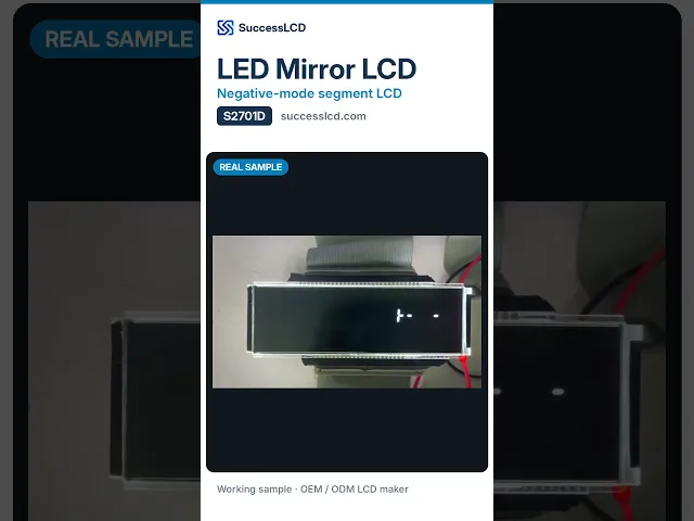
The real S2701D sample in operation. The YouTube player loads when you press play.
01 / REFERENCE CONFIGURATION
A reference configuration for discussing your LCD project. Final specifications are subject to project confirmation.
Need different digits, icons or outline? See custom segment LCD design.
| Model reference | S2701D |
|---|---|
| Display mode | Negative |
| Polarizers (front / rear) | Transmissive / transmissive (needs backlight) |
| Viewing direction | 12 o’clock |
| Operating temperature | −20°C to +70°C |
| LCD operating voltage | 3.3 V |
| Drive condition | 1/4 duty, 1/3 bias |
| Connector | Metal pins |
| Pin / contact pitch | 2.54 mm pitch |
| Viewing area | 94.59 × 29.0 mm minimum |
| Glass outline | 98.59 × 36.0 mm |
02 / OEM DESIGN
Bring your requirements. We will review the configuration with you.
Share the digits, symbols, icons or graphics needed for your LED mirror interface.
Define the viewing window, available space, mounting method and connection position.
Confirm your host controller, supply, drive method and backlight requirements before sampling.
03 / APPLICATION DIRECTION
S2701D is presented as a reference for LED mirrors. Review the drawing-based specification and the six product views, then tell us what your LED mirror needs to show.
Identify the readings, status indicators and control feedback your users need to see.
Coordinate the display opening, viewing direction and connection with the complete product.
Agree the display configuration and sample requirements with our team.
ENGINEERING NOTES
How S2701D relates to LCD mode, drive, connection and integration choices, with links to the SuccessLCD engineering guides.
4 common electrodes share the segment lines. Set the controller to the duty, bias, voltage and frame frequency listed in the specification. Duty and bias explained →
A negative LCD needs a backlight; the look is close to a VFD or LED readout. VFD vs LCD →
04 / PRODUCT SUPPORT
This page presents a reference design for OEM discussions. The final specification and available customization are confirmed against your project requirements.
Include S2701D, your application, display artwork, enclosure dimensions, electrical requirements, sample and production quantities, and target schedule.
The reference drawing for S2701D specifies a 1/4 duty, 1/3 bias drive condition and a 12 o’clock viewing direction. The reference is offered at 3.3 V LCD operating voltage with an operating temperature of −20°C to +70°C. The rear polarizer is transmissive, so the display is designed to be used with a backlight. These values can be adjusted for your project.
YOUR NEXT LCD PROJECT
Start with S2701D and tell us what your product needs.