
Zebra contact design
The top and bottom contact rows use a 1.00 mm pitch. Specify the elastomer connectors, compression and PCB pads together with the housing design.
Navigate
Rotate, zoom and inspect the product. Loads on request.
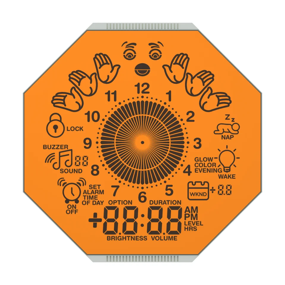
Front rendering of S3113D, showing the octagonal glass and the all-segment clock artwork with the dial, ring segments and icon groups. Materials and fine geometry are visual references for the OEM project.
OEM DISPLAY REFERENCE
S3113D has an octagonal glass outline with a 1–12 dial, a ring of radial segments and a four-digit time field. Legends include alarm, sound, nap, wake, brightness and volume, and zebra contact ledges run along the top and bottom edges.
Images, 3D geometry and listed parameters are OEM reference information. Final dimensions, electrical requirements, optical configuration and construction are confirmed for your project.
Short product video. Playback starts when you press play.
01 / REFERENCE CONFIGURATION
A reference configuration for discussing your LCD project. Final specifications are subject to project confirmation.
| Model reference | S3113D |
|---|---|
| Glass outline | 74.80 ± 0.20 × 74.80 ± 0.20 mm (octagonal) |
| Front glass height | 70.80 ± 0.20 mm |
| Corner chamfer | 21.91 ± 0.50 mm |
| Minimum viewing area | 71.80 × 67.80 mm |
| Maximum LCD thickness | 2.80 mm max |
| Contact pitch | 1.00 mm |
| Display type | STN (yellow-green) |
| Display mode | Positive, transflective |
| Connection | Zebra (elastomer) contacts |
| LCD operating voltage | 3.3 V |
| Drive condition | 1/8 duty, 1/4 bias |
| Frame frequency | 64 Hz |
| Viewing direction | 12 o'clock |
| Operating temperature | 0 to +50 °C |
| Storage temperature | −10 to +60 °C |
02 / OEM DESIGN
Bring your requirements. We will review the configuration with you.
The top and bottom contact rows use a 1.00 mm pitch. Specify the elastomer connectors, compression and PCB pads together with the housing design.
Match the bezel opening to the chamfered octagonal outline and the minimum viewing area so the outer dial icons remain visible.
Confirm your host controller, supply, drive method and backlight requirements before sampling.
03 / APPLICATION DIRECTION
The source application is clocks. The dial, alarm and wake-up icons are fixed display artwork; timekeeping, sound and lighting functions belong to the clock electronics. The orange appearance in the images and sample video shows a lit display state; a backlight is not listed for this LCD.
ENGINEERING NOTES
How S3113D relates to LCD mode, drive, connection and integration choices, with links to the SuccessLCD engineering guides.
Super twisted nematic glass: keeps contrast at higher multiplex ratios, with a yellow-green, gray or blue appearance. Compare TN, HTN, STN, FSTN, DFSTN and VA →
8 common electrodes share the segment lines. Set the controller to the duty, bias, voltage and frame frequency on the drawing. Duty and bias explained →
An elastomeric connector presses the glass contacts against PCB pads; the housing or a bracket provides the clamping force. LCD connection types →
Readable by daylight and with a backlight in the dark. Transflective LCD display →
04 / PRODUCT SUPPORT
The reference lists 3.3 V LCD operating voltage and 1/8 duty, 1/4 bias, at 64 Hz frame frequency. Check these requirements against your LCD driver; final electrical requirements are confirmed for the project.
No backlight is listed for this bare LCD reference. Lighting, timekeeping and sound are part of the finished clock design and are specified separately.
YOUR NEXT LCD PROJECT
Share your required display content, enclosure space, drive arrangement, operating environment and target quantity.


