
What Is a TFT LCD Display? Structure and How It Works
A TFT LCD display is a liquid-crystal display that uses a thin-film-transistor active-matrix backplane to address individual subpixels. The TFT switch and storage capacitance set and hold each subpixel voltage, while the liquid-crystal and polarizer stack modulates light from the backlight. TFT describes the addressing method; LCD describes the light-modulating display.
For OEM engineers, that definition explains the operating principle but not the complete module specification. Resolution, interface, viewing behavior, backlight, temperature range, touch stack and mechanical construction still depend on the exact part. When you are ready to compare real products, use the TFT LCD module overview.
- TFT means thin-film transistor and identifies the active-matrix addressing backplane.
- LCD means liquid-crystal display and identifies the optical light-modulation method.
- A TFT LCD combines both functions. Not every LCD uses TFT addressing, and the TFT label alone does not define module performance.
What does TFT LCD mean?
TFT LCD means thin-film-transistor liquid-crystal display. In this architecture, thin-film transistors form an active-matrix backplane behind the liquid-crystal cell. The backplane selects and holds the electrical state of each subpixel; it does not create the visible light by itself.
The LCD portion controls transmitted or reflected light through the liquid-crystal layer and polarizers. In a typical transmissive color module, an LED backlight supplies light and red, green and blue color filters form the visible subpixels. Passive-matrix LCDs also exist, so “LCD” does not automatically mean “TFT LCD.”
Main layers and components of a TFT LCD
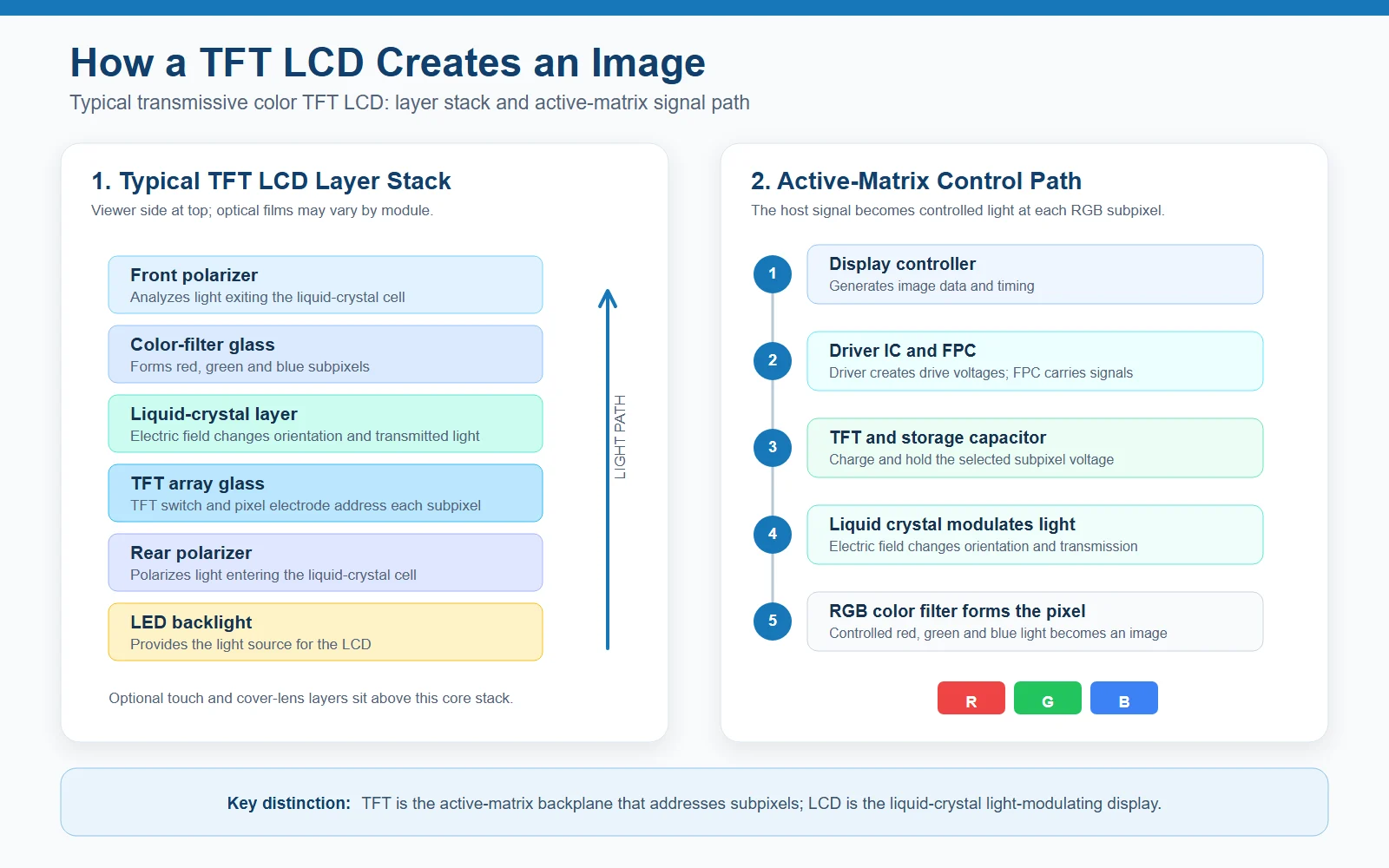
A practical module combines the optical cell, active-matrix array, illumination and driver electronics. The sequence below is simplified from the viewer side toward the backlight side.
| Layer or component | Main function | OEM implication |
|---|---|---|
| Front polarizer | Analyzes light after it passes through the liquid-crystal cell. | Surface treatment and polarizer selection affect reflection, contrast and environmental durability. |
| Color-filter substrate | Forms red, green and blue subpixels for a color image. | Color performance depends on the complete filter, backlight and drive system. |
| Liquid-crystal cell | Changes molecular orientation under an electric field and thereby changes transmitted light. | Viewing behavior, response and temperature performance depend on the selected cell design. |
| TFT-array substrate | Carries the TFT switches, pixel electrodes, storage capacitance and row and column conductors. | Array design and manufacturing quality influence resolution, uniformity and pixel-defect performance. |
| Rear polarizer | Polarizes light entering the liquid-crystal cell. | It works with the front polarizer and cell mode to produce the intended optical response. |
| Optical films and LED backlight | Distribute and supply illumination for a transmissive LCD. | Luminance, uniformity, power, dimming, heat and backlight life must be checked at module level. |
| Driver IC and FPC | The driver converts image data into gate and source drive signals; the FPC carries electrical connections. | Confirm interface, timing, voltage, pixel format, initialization, pinout and host compatibility. |
Module production also includes array fabrication, cell assembly, driver attachment, backlight integration and inspection. See the TFT LCD module manufacturing process for that production sequence.
How does a TFT LCD work?
The active matrix converts image data into a held voltage at each selected subpixel. The optical stack then converts that electrical state into visible brightness and color.
- The host sends image data and timing. The display controller transfers the required pixel data through the module interface.
- The driver IC creates gate and source signals. Gate drivers select a row, while source drivers apply the corresponding column voltages.
- Selected TFT switches charge the subpixels. Each active switch transfers voltage to its pixel electrode and storage capacitance, which helps hold the state between refreshes.
- The electric field changes liquid-crystal orientation. The liquid-crystal cell changes how polarized light travels through the stack; the TFT does not directly create or block the light.
- Controlled RGB light forms the image. Red, green and blue subpixels transmit different light levels, and their combined intensities create the visible pixel color.
The electrical interface is a transport choice rather than part of the liquid-crystal physics. For host-board planning, compare the MIPI DSI, LVDS and RGB LCD interface differences and validate the exact timing and pinout of the chosen module.
TFT vs LCD: why the terms are not alternatives
“TFT versus LCD” compares two different functions. TFT describes an active-matrix addressing backplane. LCD describes a display that modulates light with a liquid-crystal cell. A TFT LCD combines them, while some LCDs use passive-matrix addressing.
TN and IPS are also not alternatives to TFT. They describe liquid-crystal operating modes that can be used within a TFT LCD. Their viewing-angle, color and response tendencies must be checked against the exact module and application; see the TN vs IPS LCD engineering comparison.
If a product only needs segments, icons or simple character information, a monochrome LCD or LCM may use a different architecture and may be a more appropriate starting point.
Advantages and limitations of TFT LCD displays
Common strengths
- Active-matrix addressing sets and holds individual subpixel states for detailed color images.
- A wide range of resolutions, mechanical formats, interfaces, backlights and touch configurations is available.
- TN, IPS and other cell designs allow different optical priorities within the TFT LCD family.
- The module can be integrated with a touch sensor, cover lens, optical bonding and application-specific mechanics.
Engineering limitations and variables
- A conventional transmissive TFT LCD needs a backlight, so luminance, power, heat and backlight life require separate qualification.
- Viewing behavior, response, contrast and temperature performance are not guaranteed by the term “TFT LCD.”
- Sunlight readability depends on luminance, reflectance, polarizers, surface treatment, bonding and enclosure design.
- Similar diagonal size and resolution do not guarantee compatible outline, connector, timing, pinout or initialization.
OEM TFT LCD selection checklist
Use the operating principle to ask better specification questions, then validate the complete module in the real product.
- Mechanical: active area, resolution, outline, thickness, orientation, mounting points and FPC exit direction.
- Optical: liquid-crystal mode, luminance, contrast, viewing directions, surface reflection and acceptable color shift.
- Electrical: interface, timing, logic voltage, pixel format, pinout, connector, initialization and host compatibility.
- Backlight: current, voltage, dimming method, power budget, thermal behavior and life definition.
- Front stack: touch technology, cover-lens material, coatings, optical bonding and sealing.
- Environment: operating and storage temperature, cold start, humidity, ESD, EMI, vibration and duty cycle.
- Lifecycle: revision control, product-change notification, end-of-life planning and replacement strategy.
- Validation: test samples with the real controller, cable, power supply, enclosure, touch stack and representative user interface.
Frequently asked questions
What does TFT LCD mean?
TFT LCD means thin-film-transistor liquid-crystal display. In a TFT LCD, the thin-film-transistor backplane and storage capacitance address and hold the voltage of each subpixel, while the liquid-crystal cell modulates light. The term describes two different functions within one display architecture.
Is TFT the same as LCD?
No. TFT describes active-matrix addressing; LCD describes the liquid-crystal light-modulation method. A TFT LCD combines them. Not every LCD uses TFT addressing because passive-matrix LCDs also exist, and TFT backplanes are not limited only to LCD technology.
Does a TFT LCD produce its own light?
Most transmissive color TFT LCDs do not emit light at the pixels. An LED backlight supplies illumination, and the liquid-crystal, polarizer and color-filter layers modulate it to create the visible image. Reflective and transflective constructions handle illumination differently.
What are the main parts of a TFT LCD module?
A typical transmissive color module includes TFT-array glass, a liquid-crystal cell, color-filter glass, front and rear polarizers, optical films, an LED backlight, driver electronics and an FPC or connector. Touch panels and cover lenses are optional system layers.
Which TFT LCD specifications matter for an OEM project?
Review active area, outline, resolution, interface, timing, luminance, viewing characteristics, temperature range, backlight, touch integration, power, connector geometry and lifecycle. Validate the selected module with the real controller, enclosure, front stack and operating conditions.
Technical references
- IEC 61747-1-2:2014 — terminology and symbols for liquid-crystal display devices.
- IEC 61747-30-1:2012 — measuring methods for transmissive liquid-crystal display modules.
Translate the display principle into module requirements
Share the active area, resolution, interface, mechanical drawing, viewing conditions, temperature range, touch stack and expected lifecycle. SuccessLCD can review the requirements against a standard or customized TFT LCD module path.
Send Your LCD RequirementsTechnical content reviewed: August 25, 2026. Specifications and operating limits must be confirmed for the selected module and test conditions.


