
Driver and viewing direction
The reference uses 1/8 duty, 1/4 bias at 3.0 V and 64 Hz, with a 12 o'clock viewing direction. Confirm the reading orientation in the housing.
Navigate
Rotate, zoom and inspect the product. Loads on request.
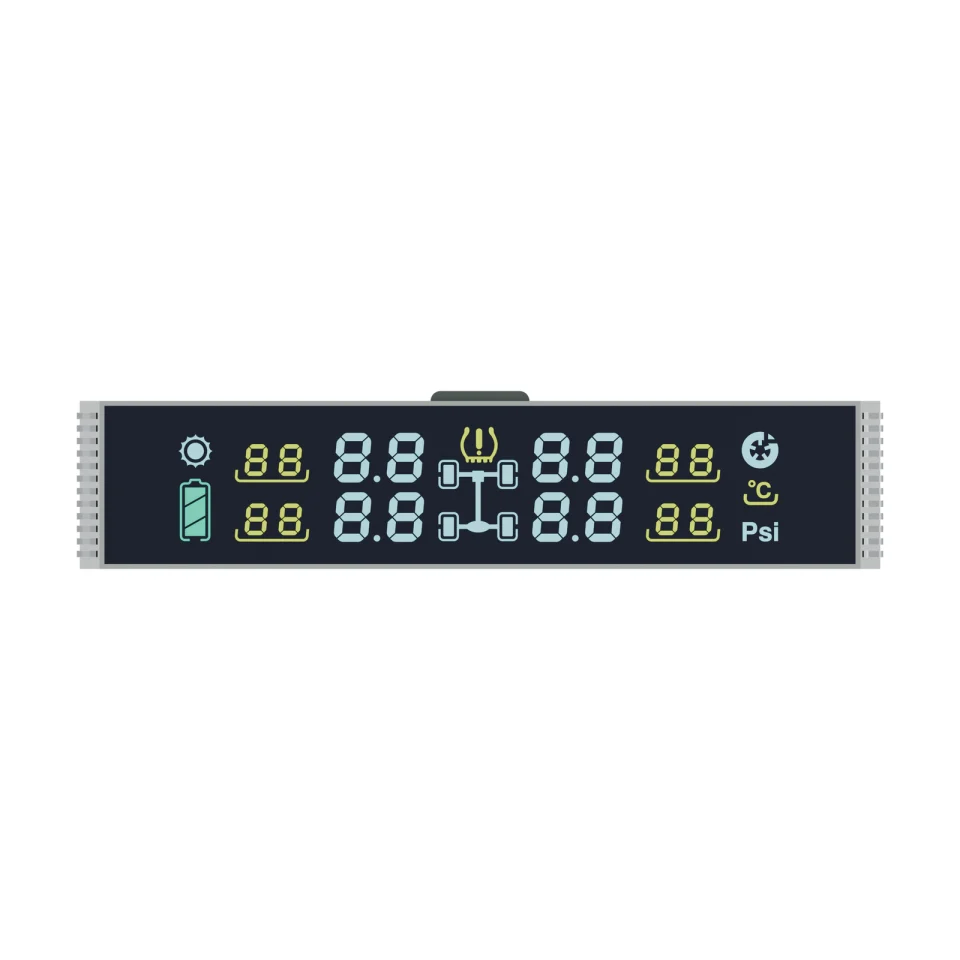
Front product rendering of S3412D, showing the four main fields, four smaller fields, axle diagram and Psi legend on a white background.
OEM DISPLAY REFERENCE
S3412D arranges four two-digit main fields and four smaller fields around a central axle diagram, with tire, battery, temperature and Psi symbols. Its drawing specifies a negative display mode and a 74.00 × 14.00 mm minimum viewing area in an 81.00 mm wide glass outline.
Images, 3D geometry and listed parameters are OEM reference information. Final dimensions, electrical requirements, optical configuration and construction are confirmed for your project.
Short product video. Playback starts when you press play.
01 / REFERENCE CONFIGURATION
A reference configuration for discussing your LCD project. Final specifications are subject to project confirmation.
| Model reference | S3412D |
|---|---|
| Display mode | Negative |
| Drive condition | 1/8 duty, 1/4 bias |
| LCD operating voltage | 3.0 V |
| Frame frequency | 64 Hz |
| Viewing direction | 12 o'clock |
| Operating temperature | −20 to +70 °C |
| Storage temperature | −30 to +80 °C |
| Front polarizer | Transmissive, adhesive |
| Rear polarizer | Transmissive, adhesive |
| Connection | Pins |
| Glass outline | 81.00 ± 0.20 × 17.00 ± 0.20 mm |
| Second glass length | 77.00 ± 0.20 mm |
| Minimum viewing area | 74.00 × 14.00 mm |
| Pin count | 24 (12 at each end) |
| Pin pitch | 1.27 mm |
| LCD thickness | Max. 2.00 mm |
| Pin length | 8.50 ± 0.50 mm |
02 / OEM DESIGN
Bring your requirements. We will review the configuration with you.
The reference uses 1/8 duty, 1/4 bias at 3.0 V and 64 Hz, with a 12 o'clock viewing direction. Confirm the reading orientation in the housing.
Twelve pins at each end on a 1.27 mm pitch. Reserve board space at both short ends and keep the 74.00 × 14.00 mm minimum viewing area clear in the window.
03 / APPLICATION DIRECTION
The source application is tire-pressure displays. The axle diagram, tire and Psi symbols are fixed segment artwork; pressure sensing, wireless reception and alarm thresholds belong to the complete system.
ENGINEERING NOTES
How S3412D relates to LCD mode, drive, connection and integration choices, with links to the SuccessLCD engineering guides.
8 common electrodes share the segment lines. Set the controller to the duty, bias, voltage and frame frequency on the drawing. Duty and bias explained →
Metal pins are soldered into the PCB, the most robust connection for segment glass. LCD connection types →
A negative LCD needs a backlight; the look is close to a VFD or LED readout. VFD vs LCD →
Digit, decimal point and icon layout set the segment count and pin map. 7-segment digit design →
04 / PRODUCT SUPPORT
The source records for this reference are not consistent on the exact liquid-crystal technology, so it is not listed here. It is confirmed together with the optical configuration for your project.
No. This page describes the LCD reference and its fixed artwork. Sensors, wireless electronics and firmware are specified separately.
YOUR NEXT LCD PROJECT
Share your required display content, enclosure space, drive arrangement, operating environment and target quantity.


