
Character LCD Modules: 16×2, 16×4 And 20×4 Guide For OEMs
Quick answer: a character LCD module is a monochrome display that shows text in a fixed grid of character cells, such as 16 characters × 2 lines (16×2), 16 × 4 or 20 × 4. Each cell is a small dot matrix, usually 5 × 8 dots, and an on-board controller draws letters, numbers and a few custom symbols from a built-in font. Many modules use an HD44780-compatible controller with a parallel interface; I²C, SPI or UART versions are also available.
Choose a character LCD when the product only needs lines of text and simple symbols. Choose a graphic LCD or a TFT when it needs free-form graphics, larger fonts or images.
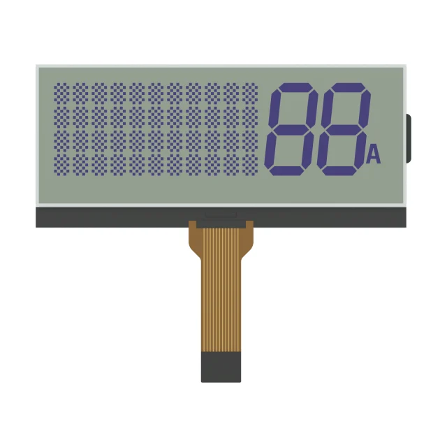
Common Character LCD Formats
| Format | Characters × Lines | Typical Use |
|---|---|---|
| 16×1 / 16×2 (often called 1602) | 16 × 1 or 16 × 2 | Simple status, setpoints and short menus |
| 16×4 | 16 × 4 | Several readings or a short menu on one screen |
| 20×2 / 20×4 (often called 2004) | 20 × 2 or 20 × 4 | Instrument and controller menus with more text per line |
| 24×2, 40×2, 40×4 | Wider lines | Larger panels; a 40×4 module commonly uses two controller sections with separate enable lines |
Formats with the same character count can still differ in outline, viewing area, character height, mounting holes and connector position, so compare drawings rather than the format name alone. For 8×1, 16×1 and 40×2 addressing, including the split 16×1 type, see 16×1, 8×1 and 40×2 character LCDs.
Interface And Pinout
Most HD44780-compatible character LCDs use a parallel bus in 8-bit or 4-bit mode. A common 16-pin arrangement is:
| Pin | Signal | Function |
|---|---|---|
| 1 | VSS | Ground |
| 2 | VDD | Logic supply |
| 3 | V0 | Contrast adjustment |
| 4 | RS | Register select (command or data) |
| 5 | R/W | Read or write |
| 6 | E | Enable strobe |
| 7–14 | DB0–DB7 | Data bus (only DB4–DB7 are used in 4-bit mode) |
| 15 / 16 | A / K | Backlight LED anode and cathode, when fitted |
This order is common but not universal: some modules place the backlight pins first, use a 14-pin header without backlight, or add an I²C adapter; see I2C character LCD adapters. Always confirm the pin table, supply voltage (5 V and 3.3 V versions exist) and timing in the module’s own datasheet.
HD44780 Commands And Initialization
HD44780-compatible controllers, such as the ST7066U, SPLC780D and KS0066, share one small instruction set. With RS low, a byte written to the module is a command; with RS high, it is character data. Timing can differ between compatible controllers, so check the module datasheet.
| Command | Hex | What it does |
|---|---|---|
| Clear display | 0x01 | Clears the display and returns the cursor to address 0; about 1.52 ms |
| Return home | 0x02 | Returns the cursor to address 0 and undoes any display shift; about 1.52 ms |
| Entry mode set | 0x04–0x07 | Cursor direction and display shift after each character; 0x06 moves the cursor right without shifting |
| Display on/off control | 0x08–0x0F | Display, cursor and blink bits; 0x0C turns the display on with the cursor off |
| Cursor or display shift | 0x10–0x1F | Moves the cursor, or scrolls the whole display left or right |
| Function set | 0x20–0x3F | Bus width, number of lines and font; 0x28 selects 4-bit, 2 lines, 5×8 dots and 0x38 the same in 8-bit mode |
| Set CGRAM address | 0x40–0x7F | Selects custom-character memory for writing |
| Set DDRAM address | 0x80–0xFF | Moves the cursor to a display position: 0x80 plus the address |
Most commands take about 37 µs at the typical oscillator frequency. Wait for that time, or read the busy flag on DB7 with RS low and R/W high. If R/W is tied to ground, fixed delays are the only option.
DDRAM addresses for each line
| Format | Line 1 | Line 2 | Line 3 | Line 4 |
|---|---|---|---|---|
| 16×2, 20×2 | 0x00 | 0x40 | – | – |
| 16×4 | 0x00 | 0x40 | 0x10 | 0x50 |
| 20×4 | 0x00 | 0x40 | 0x14 | 0x54 |
To move the cursor to the start of line 2, send 0x80 + 0x40 = 0xC0. On a 20×4 display, lines 3 and 4 start with 0x94 and 0xD4. Because line 3 continues line 1 in memory, text that runs past the end of line 1 on a 20×4 appears on line 3, not line 2. A 40×4 module uses two controller sections, each addressed like a 40×2 display with its own enable line.
4-bit initialization sequence
- Wait at least 40 ms after the supply rises (the original datasheet gives 15 ms after 4.5 V and 40 ms after 2.7 V).
- Send the high nibble 0x3 and wait more than 4.1 ms.
- Send 0x3 again and wait more than 100 µs.
- Send 0x3 a third time.
- Send 0x2 to switch to 4-bit mode. From here every byte is sent as two nibbles, high nibble first.
- Send function set 0x28, display off 0x08, clear 0x01 (wait about 1.52 ms), entry mode 0x06, then display on 0x0C.
This sequence works whether the controller powered up in 8-bit or 4-bit mode, which is why it starts with three 0x3 nibbles. If the display shows a row of solid blocks and nothing else, initialization has not completed; if every pixel is dark, the contrast is set too strong.
Custom characters
CGRAM holds eight custom 5×8 characters with codes 0x00 to 0x07. To define character n, send the Set CGRAM address command 0x40 + n × 8, write eight bytes with the dot pattern in the lower five bits of each row, then send a Set DDRAM address command before writing text again. Writing code n to the display then shows the custom character.
How To Specify A Character LCD For An OEM Product
- Content. Count the characters and lines the longest screen needs, and list any custom symbols. HD44780-compatible controllers store up to eight user-defined characters at a time, and the built-in font set varies by controller version.
- LCD mode and backlight. Choose positive or negative mode and the LC type (STN, FSTN and others), and whether a backlight is needed. See the monochrome LCD type guide.
- Interface. Match the parallel, I²C, SPI or UART interface and the logic voltage to the host.
- Mechanics. Check outline, viewing area, mounting and the connection method (pin header, FPC or zebra; see FPC vs FFC and LCD connection types).
- Environment. State operating and storage temperature, viewing direction and lighting so the LC fluid, polarizer and backlight can be reviewed.
SuccessLCD Character LCD Reference
S4132D is a 20 × 4 character STN positive-mode LCD glass reference. It uses ITO contact areas for a zebra connection and a 77.30 × 26.00 mm minimum viewing area. As a glass reference it does not include a controller board; controller, backlight and connection are defined for the project. For custom artwork or mixed text and icons, see custom segment LCD.
Video: Character LCD Modules Explained
This short SuccessLCD explainer shows what 16×2, 16×4 and 20×4 mean, how text cells and the on-board controller work, the common 16-pin parallel interface and what to specify, with the S4132D 20 × 4 character glass reference.
Character LCD FAQs
What does 16×2 or 1602 mean on an LCD?
It means the display shows 16 characters on each of 2 lines. “1602” is a common shorthand for the same format, and “2004” refers to 20 characters × 4 lines.
What is the difference between a character LCD and a graphic LCD?
A character LCD shows text in fixed cells from a built-in font. A graphic LCD addresses every pixel in a dot-matrix area, so it can show any font size, icons and simple graphics, at the cost of more host-side drawing work.
Can a character LCD use I²C instead of a parallel bus?
Yes. Some modules have a native serial controller, and many parallel modules are paired with an I²C adapter. Confirm the controller, address and logic voltage for the exact module.
Can a character LCD show custom symbols?
Yes, within limits. HD44780-compatible controllers allow up to eight user-defined characters at a time. Products that need many symbols or icons may be better served by a custom segment LCD or a graphic LCD.
What should I send for a custom character LCD quotation?
Send the character format, sample screens, LCD mode and color, backlight needs, interface and voltage, outline and viewing area, connection method, operating environment and expected quantity. See what to include in an LCD module RFQ.
How do I move the cursor to the second line of a 16×2 LCD?
Send the Set DDRAM Address command 0xC0, which is 0x80 plus the line 2 start address 0x40. On a 20×4 display, line 3 starts with 0x94 and line 4 with 0xD4.
Need a character LCD for your product? Browse monochrome LCD and LCM references or send your character LCD requirements for an engineering review. For a custom character format or backlight, see custom LCD modules.