
Driver and viewing direction
The reference uses 1/4 duty, 1/3 bias at 3.3 V and 64 Hz, with a 6 o'clock viewing direction.
Navigate
Rotate, zoom and inspect the product. Loads on request.
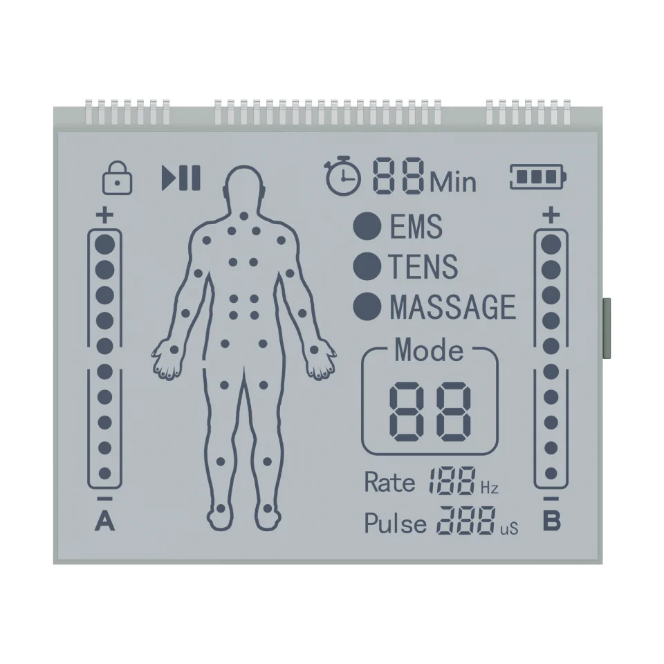
Front product rendering of S3817D, showing the body outline, mode legends and A/B intensity scales on a white background.
OEM DISPLAY REFERENCE
S3817D shows a body outline with point markers, EMS, TENS and MASSAGE legends, a two-digit Mode field, a minute timer, Rate and Pulse fields and two dotted intensity scales marked A and B, with lock, play/pause and battery icons. The drawing specifies HTN positive mode and 32 pins in three groups.
Images, 3D geometry and listed parameters are OEM reference information. Final dimensions, electrical requirements, optical configuration and construction are confirmed for your project.
Short product video. Playback starts when you press play.
01 / REFERENCE CONFIGURATION
A reference configuration for discussing your LCD project. Final specifications are subject to project confirmation.
| Model reference | S3817D |
|---|---|
| Display mode | HTN, positive |
| Drive condition | 1/4 duty, 1/3 bias |
| LCD operating voltage | 3.3 V |
| Frame frequency | 64 Hz |
| Viewing direction | 6 o'clock |
| Operating temperature | 0 to +50 °C |
| Storage temperature | −10 to +60 °C |
| Front polarizer | Transmissive, adhesive |
| Rear polarizer | Transmissive, adhesive |
| Connection | Pins |
| Glass outline | 54.00 ± 0.20 × 45.00 ± 0.20 mm |
| Front glass height | 43.00 ± 0.20 mm |
| Minimum viewing area | 51.40 × 40.40 mm |
| Pin count | 32 (groups of 7, 18 and 7) |
| Pin pitch | 1.27 mm |
| LCD thickness | Max. 2.80 mm |
| Pin length | 4.30 ± 0.50 mm |
02 / OEM DESIGN
Bring your requirements. We will review the configuration with you.
The reference uses 1/4 duty, 1/3 bias at 3.3 V and 64 Hz, with a 6 o'clock viewing direction.
Thirty-two pins in groups of 7, 18 and 7 on a 1.27 mm pitch within each group, extending 4.30 ± 0.50 mm towards the rear.
03 / APPLICATION DIRECTION
The source application is massager displays. The legends and body artwork are fixed segments; stimulation modes, output and any treatment-related functions belong to the device and its own approvals.
ENGINEERING NOTES
How S3817D relates to LCD mode, drive, connection and integration choices, with links to the SuccessLCD engineering guides.
High twisted nematic glass: better contrast and a wider viewing angle than TN at a similar cost. Compare TN, HTN, STN, FSTN, DFSTN and VA →
4 common electrodes share the segment lines. Set the controller to the duty, bias, voltage and frame frequency on the drawing. Duty and bias explained →
Metal pins are soldered into the PCB, the most robust connection for segment glass. LCD connection types →
04 / PRODUCT SUPPORT
No. It is a display reference. EMS, TENS and massage functions, output levels and any medical approvals belong to the complete device.
They are two fixed columns of dot segments. Their meaning is defined by the device firmware.
YOUR NEXT LCD PROJECT
Share your required display content, enclosure space, drive arrangement, operating environment and target quantity.


