
How to Improve TFT LCD Sunlight Readability
Quick answer: Improve TFT LCD sunlight readability with high-brightness backlights, AR/AG treatment and optical bonding to reduce glare and preserve contrast.

On this page
- Why a TFT LCD can look washed out in direct sunlight
- Build sunlight readability around two controls
- 1. Increase useful display brightness
- 2. Reduce surface and internal reflections
- How to select a sunlight-readable TFT LCD solution
- RFQ details that make the review faster
- Frequently asked questions
- Plan the optical stack before the sample build
Why a TFT LCD can look washed out in direct sunlight
A transmissive TFT LCD relies on its backlight. In strong ambient light, the display must compete with sunlight while the outer cover glass, touch panel and internal air interfaces can create reflections. The visible result is lower perceived contrast, glare and a screen that looks pale even when its nominal brightness appears adequate on a datasheet.
For industrial HMI panels, EV chargers, portable terminals and outdoor equipment, sunlight readability is therefore an optical-system decision rather than a single brightness specification.
Build sunlight readability around two controls
- Increase useful emitted light: review the backlight, light guide, optical films, drive current and thermal path.
- Reduce reflected light: review the cover surface, touch stack, air gaps and optical bonding before the enclosure is frozen.
1. Increase useful display brightness
Use a high-brightness LED backlight with a thermal plan
Many indoor TFT LCD modules are selected around moderate brightness. Outdoor or high-ambient-light projects commonly need a higher-luminance backlight, but the target must be chosen against installation angle, cover lens, daylight exposure and acceptable power draw. A figure such as 1,000 nits is a starting point for engineering review, not a universal sunlight-readability guarantee.
The module review should cover LED efficiency, the light-guide plate, reflector and diffuser films, brightness-enhancement films, drive current and brightness uniformity. It must also include the thermal route from the backlight into the mechanical design. Higher drive current can increase heat and accelerate luminance decay if the enclosure cannot remove that heat effectively.
For a product-led starting point, review our high-brightness TFT LCD module options with the final application environment rather than selecting only by a peak nit value. For the LED, light-guide, optical-film and edge-lit versus direct-lit design choices behind that specification, see our LCD backlight module guide.
Consider transflective TFT when power and daylight use matter
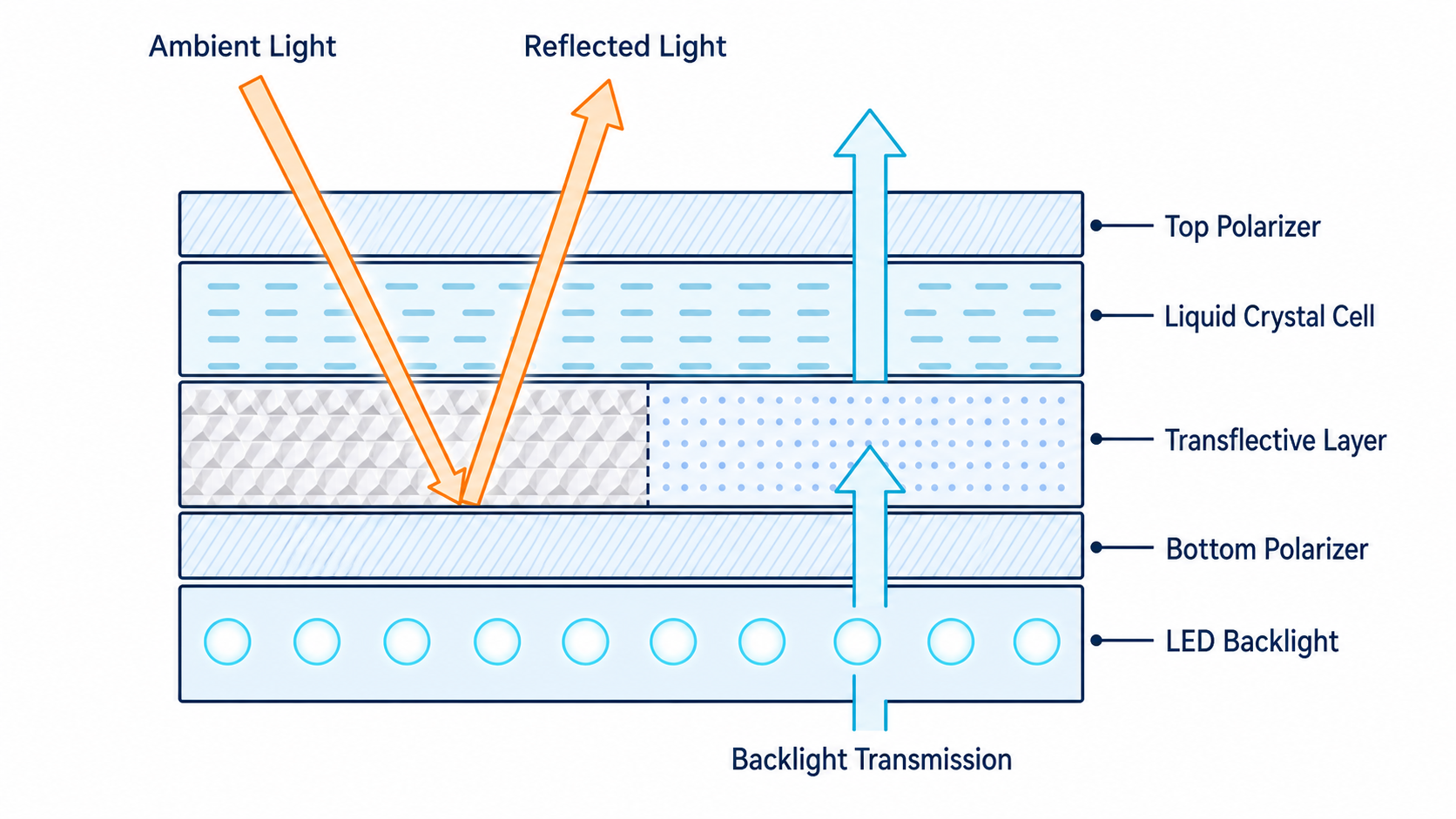
A transflective TFT LCD combines transmissive and reflective behavior. In lower light it uses the backlight like a conventional TFT. In bright ambient light, part of the incoming light can be reflected through the display structure to support visibility. This can be useful for battery-powered terminals, field instruments and applications that move between indoor and outdoor conditions.
For a direct comparison of the three optical modes and their OEM trade-offs, review our transflective LCD display selection guide.
Transflective technology is not an automatic substitute for a high-brightness module. Color performance, available module sizes, cost, viewing conditions and the final front stack should be checked together.
2. Reduce surface and internal reflections
Choose AR and AG treatment for different jobs
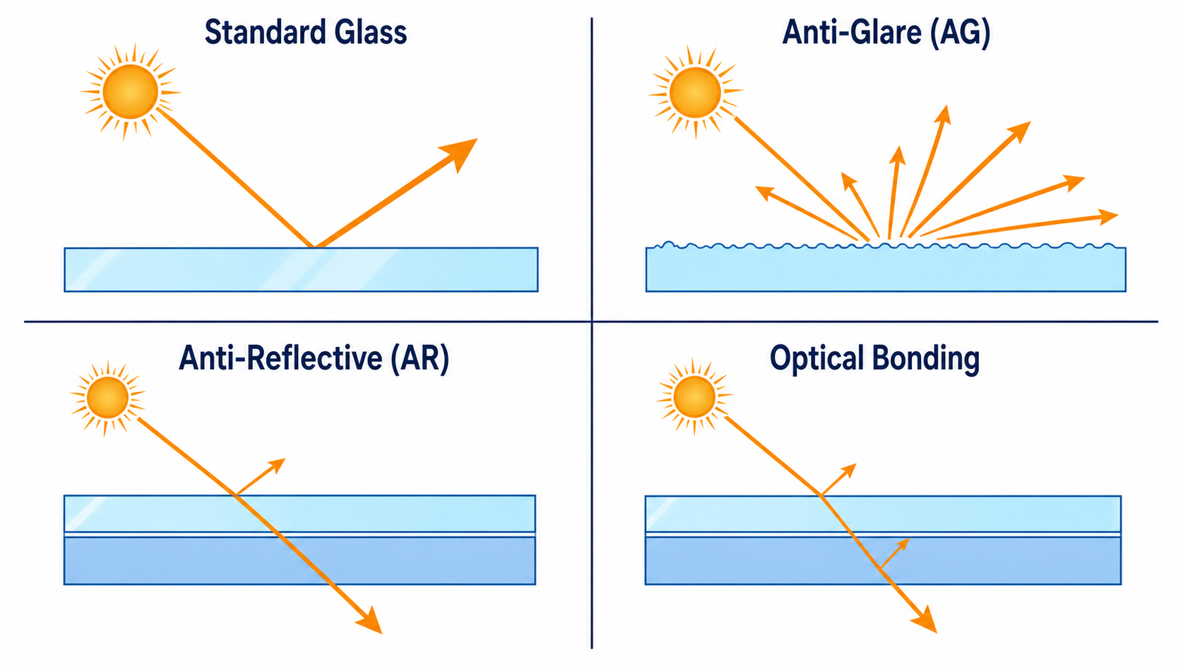
Anti-reflective (AR) treatment is used to lower specular reflection from a glass surface and preserve contrast. Anti-glare (AG) treatment uses a micro-textured surface to spread reflected light and reduce mirror-like glare. AG can be useful for functional industrial displays, while AR is often considered where optical clarity is the first priority.
Neither treatment should be chosen in isolation. Cover-lens material, touch panel construction, expected cleaning process, haze tolerance and viewing distance can all change the preferred surface treatment.
Use optical bonding to remove reflective air gaps
Air gaps between the cover lens, touch panel and LCD create additional reflective interfaces. Optical bonding fills an intended gap with optically clear adhesive or resin, reducing internal reflections and helping the front stack behave more like one optical system. It can also improve the perceived touch alignment and reduce sensitivity to dust or condensation in the front stack.
Bonding introduces process, rework and yield considerations, so it is most valuable when the application environment justifies it. Compare the options in our optical bonding versus air-gap LCD guide, then review the cover lens and touch requirements together.
How to select a sunlight-readable TFT LCD solution
| Project condition | First optical stack to review | Key engineering question |
|---|---|---|
| Outdoor industrial HMI or EV charger | High-brightness TFT, AR or AG cover glass, optional optical bonding | Can the enclosure remove backlight heat while maintaining contrast at the intended viewing angle? |
| Battery-powered handheld terminal | Transflective TFT or efficient high-brightness TFT, low-reflection front stack | How can daylight readability improve without compromising operating time? |
| Indoor equipment with occasional glare | Moderate brightness TFT with selected AR or AG treatment | Is full bonding necessary, or is surface reflection the actual problem? |
| Touch display with thick cover lens | Brightness review, cover lens, PCAP touch and bonding as one stack | Will parallax, internal reflection or touch behavior limit the perceived result? |
RFQ details that make the review faster
A useful sunlight-readability RFQ should include more than a target brightness. Send the display size and resolution, interface, target luminance, operating temperature, expected sunlight exposure, cover-lens drawing, touch requirement, enclosure limits, annual quantity and project stage. This gives the engineering team enough context to compare a standard high-brightness module, a transflective option or a custom optical stack.
Use our TFT LCD RFQ checklist to prepare the technical details, or review touch and cover lens options before locking the front assembly.
Frequently asked questions
Is a 1,000-nit TFT LCD always sunlight readable?
No. Brightness is important, but the result also depends on cover-glass reflection, touch and lens layers, ambient light direction, the optical stack and enclosure heat management.
Can optical bonding replace a higher-brightness backlight?
Optical bonding reduces reflection losses, but it does not create emitted light. Many outdoor projects need both an appropriate luminance target and a lower-reflection front stack.
When is transflective TFT LCD worth considering?
It is worth evaluating for products that operate in bright daylight and also need controlled power use, especially portable and field equipment. Availability, color expectations, cost and application requirements should be reviewed before selection.
Plan the optical stack before the sample build
Sunlight readability is easier to solve before the module, touch panel, cover lens and enclosure are fixed. Review sunlight-readable TFT LCD paths, or send an LCD RFQ with the application environment, brightness target and front-stack requirements for a practical review.


