
TFT-LCD Array Materials: Glass, Metal, a-Si, SiNx, and ITO
TFT-LCD Array materials determine whether the backplane can deliver stable switching, reliable electrical contact, high optical transmission, and process compatibility. This material view focuses on glass substrate, conductive metal films, nonmetal films, and ITO transparent conductive film.
On this page
Key Takeaways
- Array materials must satisfy electrical, optical, chemical, and thermal process requirements.
- Alkali-free glass protects TFT characteristics from mobile alkali-ion effects.
- a-Si, N+ a-Si, SiNx, metal stacks, and ITO each solve a different backplane function.
Alkali-Free Glass Substrate
The glass substrate must support high light transmission, thermal stability, chemical resistance, and large-format processing. TFT-LCD glass must be alkali-free because Na and K ions can migrate and disturb TFT behavior.
- High optical transmission supports panel light efficiency.
- Thermal stability helps keep the glass dimensionally stable during Array processing.
- Chemical resistance protects the glass during acid, alkali, cleaning, and etching steps.
- Alkali-free composition reduces sodium and potassium ion risks.
Conductive Metal Films
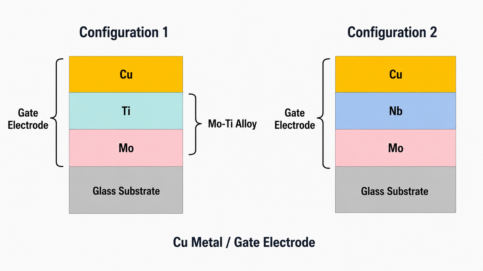
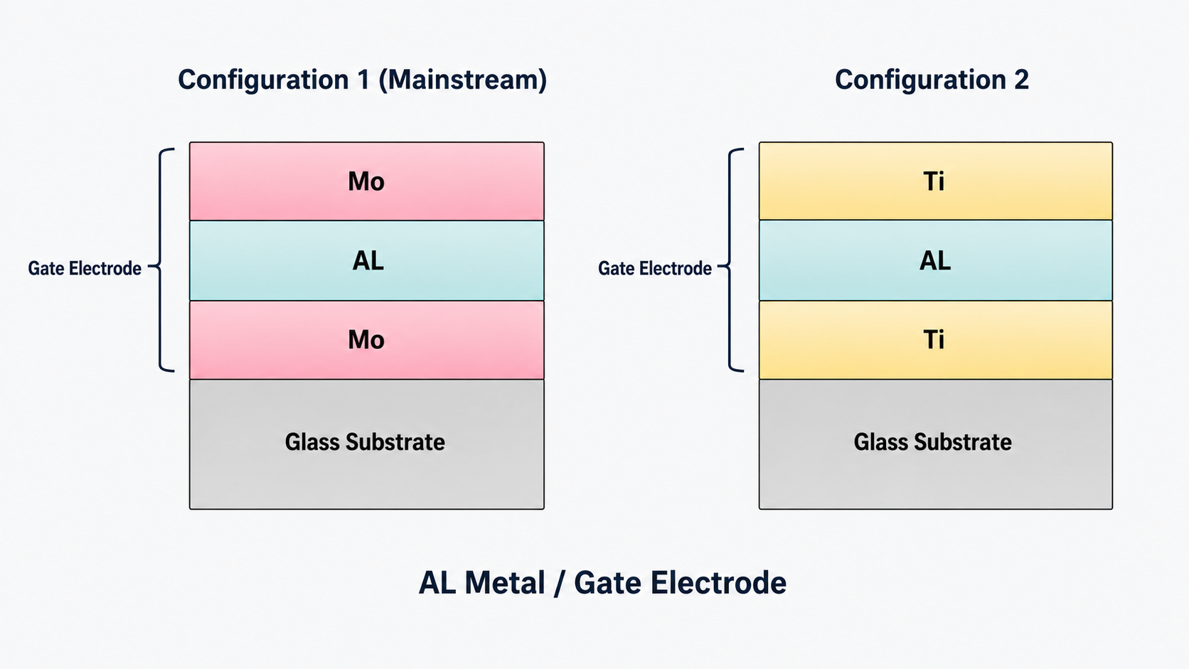
Gate and Source/Drain electrodes are usually composite metal stacks rather than single pure-metal layers. Al and Cu act as core conductive materials, while Mo, Ti, and Nb can improve adhesion, block diffusion, and stabilize interfaces.
a-Si and N+ a-Si Semiconductor Films
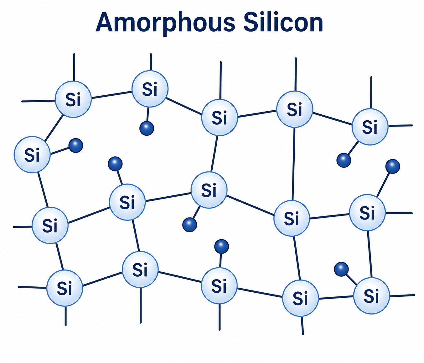
The a-Si semiconductor forms the TFT channel. N+ a-Si is added between the semiconductor and S/D metal to reduce contact resistance and improve current transfer. In practical a-Si TFT design, intrinsic a-Si and N+ a-Si play separate channel and ohmic-contact roles.
SiNx Insulating Film
SiNx serves as an insulating and protective layer. It helps block moisture diffusion and prevents sodium and oxygen from entering the a-Si TFT device. It also needs a stable interface with the semiconductor layer and compatibility with TFT deposition and etching processes.
ITO Transparent Conductive Film
ITO is a transparent conductive oxide made from indium oxide and tin oxide, commonly formulated at about 90:10 In2O3 to SnO2. It is used for pixel electrodes, common electrodes, and touch electrodes because it combines conductivity and transparency.
- Pixel-electrode ITO requires suitable sheet resistance.
- ITO transmittance is a key optical metric and is commonly specified above 80 percent.
- ITO must maintain chemical and thermal stability through process and storage.
- Moisture control matters because ITO can absorb water vapor and react with carbon dioxide.
Frequently Asked Questions
Why does TFT-LCD use alkali-free glass?
Alkali-free glass reduces Na and K ion migration risks, supporting stable TFT characteristics and reliable LCD cell behavior.
What does N+ a-Si do?
N+ a-Si forms an ohmic contact layer between the a-Si semiconductor and S/D electrodes, reducing contact resistance and improving current transfer.
Why is ITO used in LCD panels?
ITO provides both transparency and conductivity, making it suitable for pixel electrodes, common electrodes, and touch electrodes.
Technical References
The following industry references support the material properties, TFT backplane terminology, and process context used in this guide.
- Applied Materials: Amorphous Silicon
a-Si has long been a dominant active-matrix TFT-LCD semiconductor; its low mobility explains why oxide and LTPS are used for higher-performance backplanes. - AGC: Glass Substrates for TFTs (AN100)
TFT-LCD glass must be alkali-free, heat resistant, chemically stable, and dimensionally stable during array fabrication. - Nippon Electric Glass: Alkali-Free Glass Substrate OA-11
Alkali-free display glass uses very low alkaline oxide content and supports dimensional stability through TFT process temperatures. - SID / Wiley: Beyond Amorphous-Silicon TFTs
a-Si mobility is limited compared with newer high-mobility TFT materials, which helps explain material trade-offs in LCD backplane design.
Related Deep-Dive Guides
- Main TFT-LCD Array process guide
- TFT-LCD Array substrate structure
- 5-mask TFT-LCD Array process flow
- TFT-LCD Array photolithography
- Copper vs aluminum Gate electrodes
Related SuccessLCD Resources
For module sourcing, translate these Array-level requirements into a practical TFT LCD module RFQ checklist before confirming size, interface, brightness, touch, operating environment, and lifecycle targets.
Need help choosing or qualifying a TFT-LCD module?
Send your display size, resolution, interface, brightness target, touch stack, operating environment, and lifecycle requirements. SuccessLCD can review feasible TFT LCD module options before sampling or tooling.


