
Copper vs Aluminum Gate Electrodes in TFT-LCD Panels
Copper and aluminum are common core conductive materials for TFT-LCD Gate electrodes. Both materials transmit charge, but they require different stack engineering to control adhesion, diffusion, hillock formation, and reliability.
On this page
Key Takeaways
- Cu is attractive when lower resistance and narrower wiring are priorities.
- Al remains a mature TFT-LCD Gate metal baseline but needs hillock and diffusion control.
- Mo, Ti, and Nb layers are not decorative: they solve adhesion, barrier, and interface problems.
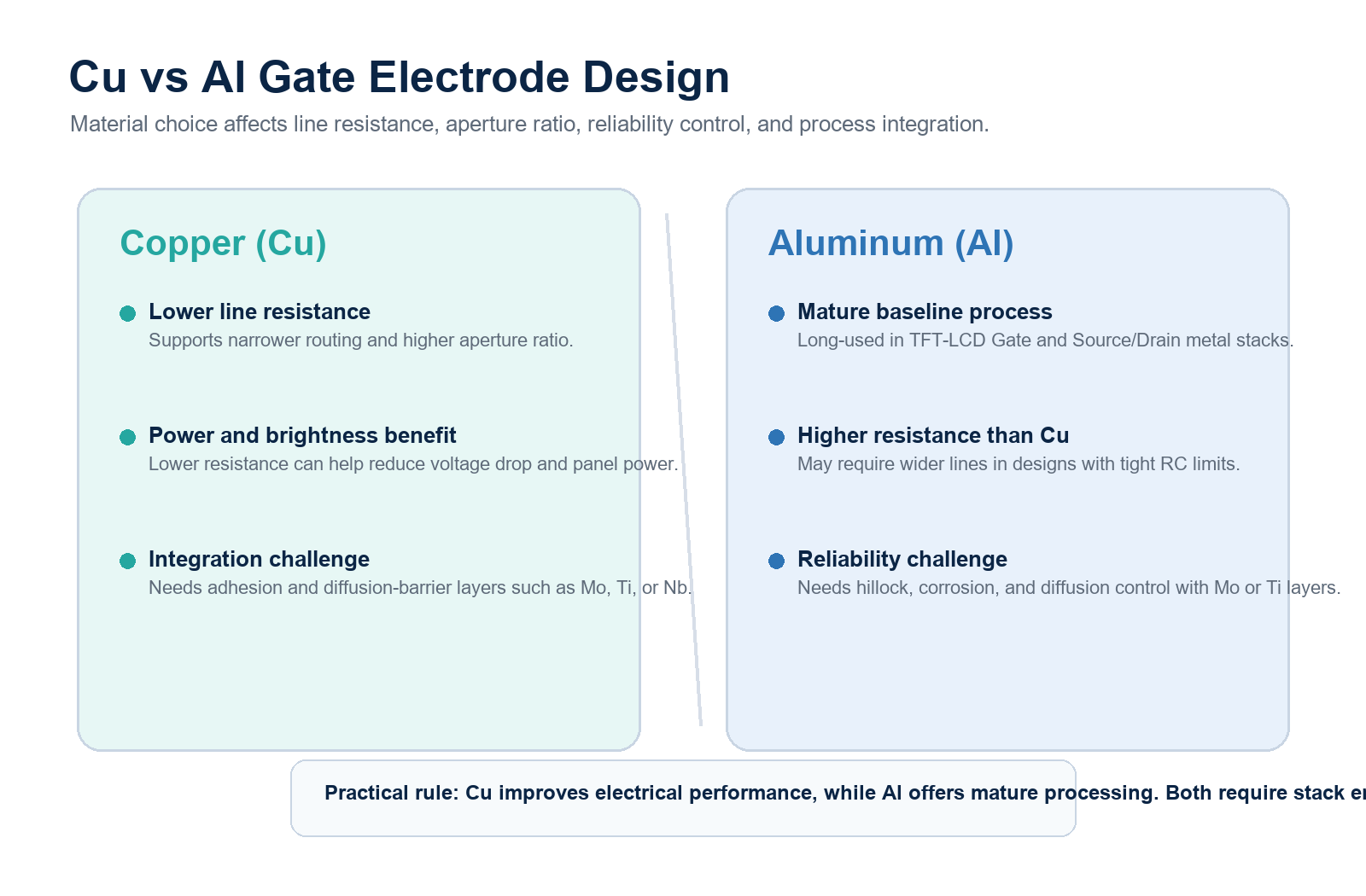
| Material | Why it is used | Main risk to control |
|---|---|---|
| Cu | Lower resistivity can reduce line width, improve aperture ratio, increase transmittance, and reduce panel power. | Poor adhesion to glass or Mo and high diffusion tendency require barrier layers. |
| Al | Mature and widely used for a long time in TFT-LCD Gate electrodes. | Thermal stress can cause hillocks; corrosion and diffusion also need control. |
Why Cu Became Attractive
Cu has higher conductivity and lower resistivity than Al. In panel design, this can reduce wiring width, improve pixel aperture ratio, improve transmittance, and help reduce power consumption.
Why Cu Needs Mo, Ti, or Nb
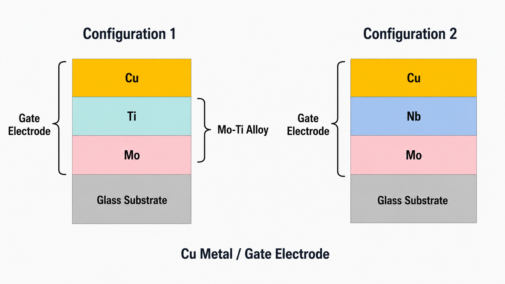
Cu does not bond well directly to glass and can suffer from diffusion problems. Mo improves adhesion to glass, while Ti and Nb can improve adhesion between Cu and Mo and act as diffusion barriers that keep Cu atoms from migrating into adjacent layers.
Why Al Needs Mo or Ti
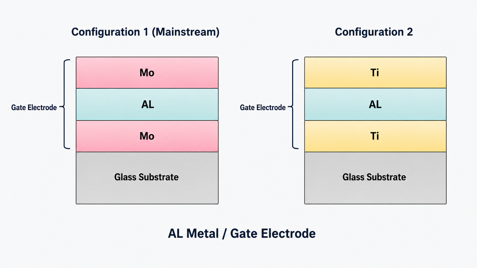
Al is mature and long-used, but it can create stress-related hillocks during heating, show chemical corrosion risk, and diffuse toward adjacent layers. Mo or Ti layers above and below Al improve adhesion, reduce diffusion, and improve interface condition.
Where to Go Next
For a broader process view, return to the TFT-LCD Array process guide. For material-stack context, continue with the TFT-LCD Array materials guide.
Frequently Asked Questions
Is copper better than aluminum for TFT-LCD Gate electrodes?
Copper has lower resistivity, which can improve line resistance and aperture ratio, but it needs more careful adhesion and diffusion-barrier design.
Why is molybdenum used with copper?
Mo improves adhesion between the metal stack and the glass substrate, especially where direct Cu-to-glass adhesion is weak.
Why does aluminum need barrier layers?
Al can form hillocks under thermal stress and can diffuse toward adjacent layers, so Mo or Ti layers are used to improve reliability.
Technical References
The following industry references support the material properties, TFT backplane terminology, and process context used in this guide.
- Applied Materials: Amorphous Silicon
a-Si has long been a dominant active-matrix TFT-LCD semiconductor; its low mobility explains why oxide and LTPS are used for higher-performance backplanes. - AGC: Glass Substrates for TFTs (AN100)
TFT-LCD glass must be alkali-free, heat resistant, chemically stable, and dimensionally stable during array fabrication. - Nippon Electric Glass: Alkali-Free Glass Substrate OA-11
Alkali-free display glass uses very low alkaline oxide content and supports dimensional stability through TFT process temperatures. - SID / Wiley: Beyond Amorphous-Silicon TFTs
a-Si mobility is limited compared with newer high-mobility TFT materials, which helps explain material trade-offs in LCD backplane design.
Related Deep-Dive Guides
- Main TFT-LCD Array process guide
- TFT-LCD Array substrate structure
- 5-mask TFT-LCD Array process flow
- TFT-LCD Array photolithography
- TFT-LCD Array materials
Related SuccessLCD Resources
For module sourcing, translate these Array-level requirements into a practical TFT LCD module RFQ checklist before confirming size, interface, brightness, touch, operating environment, and lifecycle targets.
Need help choosing or qualifying a TFT-LCD module?
Send your display size, resolution, interface, brightness target, touch stack, operating environment, and lifecycle requirements. SuccessLCD can review feasible TFT LCD module options before sampling or tooling.


