
TFT-LCD Backplane Guide
TFT-LCD Array Substrate Structure: Layers & Pixel Circuit
Updated · Technical Guide Reviewed.
A TFT-LCD array substrate is the active glass backplane containing the pixel-switching transistors, scan lines and data lines. A selected TFT lets the data signal charge a pixel; the pixel and storage capacitance help hold its voltage until the next refresh.
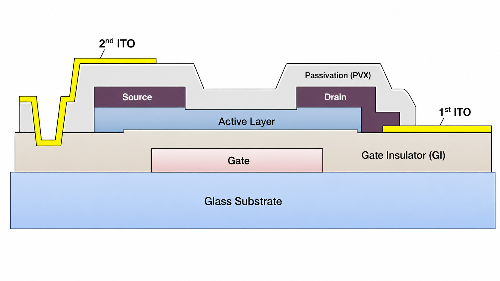
Read The Cross-Section: Start at the glass and follow the gate, insulator, semiconductor, source/drain metal, passivation and transparent electrodes. The table below explains each function. This representative bottom-gate IPS diagram shows one architecture; layer order and electrode arrangement vary by panel.
On this page
Main Layers In A TFT-LCD Array Substrate
The physical stack builds a transistor switch and transparent pixel electrode on display glass. Each deposited and patterned layer has a distinct electrical or protective role. AGC describes why TFT glass needs low alkali content and dimensional stability; those substrate requirements are separate from the finished module's interface or touch configuration.
| Layer Or Feature | Function In The Backplane |
|---|---|
| Glass substrate | Provides the flat, dimensionally stable base for thin-film processing and the pixel matrix. |
| Gate metal and scan lines | Carry the row-selection signal that switches a line of TFTs on during pixel addressing. |
| Gate insulator | Electrically separates the gate from the semiconductor and forms the TFT gate dielectric. |
| Semiconductor active layer | Forms the transistor channel whose conductivity changes with the applied gate voltage. |
| Source/drain metal and data lines | Bring the column data voltage to the selected TFT and pass it toward the pixel electrode. |
| Passivation and contact via | Protect the TFT structure while a patterned opening connects the circuit to the transparent electrode. |
| ITO pixel and common electrodes | Create the electric field that controls the liquid-crystal orientation; the arrangement depends on the display mode. |
How The Pixel Circuit Works
The cross-section shows the device layers; the pixel matrix shows how the same TFT switch is repeated across rows and columns.
- The scan line selects a row. The gate driver applies a voltage to one scan line, turning on the TFTs in that row.
- The data line writes the pixel voltage. The source driver sends the required voltage down each data line and through the selected TFT.
- The pixel holds the state. After the TFT switches off, the pixel capacitance and storage capacitance help maintain the voltage until the next refresh cycle.
This per-pixel switch-and-hold behavior distinguishes an active matrix from passive row-and-column multiplexing. See the active-matrix versus passive-matrix LCD comparison for differences in resolution, response, drive complexity and typical use.
Important distinction: the array substrate controls pixel voltage. The complete optical response also depends on the liquid-crystal layer, opposing electrode, color filter, alignment layers and polarizers.
Bottom-Gate And Top-Gate TFT Structures
In a bottom-gate, or inverted-staggered, TFT, the gate electrode is below the semiconductor channel. This arrangement is widely associated with mature large-area amorphous-silicon TFT-LCD production. In a top-gate TFT, the gate is above the channel, so the layer order and fabrication sequence differ.
The diagram on this page represents one bottom-gate IPS structure. It should be used to understand the function of the layers, not as a universal cross-section or a production drawing for every panel.
Structure Versus Array Process
This page explains the completed layer stack and pixel circuit. For the fabrication sequence—deposition, coating, exposure, development, etching and stripping—continue to the main TFT-LCD Array process guide.
Frequently Asked Questions
What Is The TFT-LCD Array Substrate?
It is the active glass backplane that carries the TFT switching matrix, scan lines, data lines, insulating and semiconductor layers, passivation and transparent electrodes used to control LCD pixels.
How Is The Array Substrate Different From The Color-Filter Substrate?
The array substrate contains the pixel-driving TFT circuit. The opposing substrate normally carries the color filters and black matrix. During cell assembly, the two substrates are aligned and the liquid-crystal layer is sealed between them.
Is Every TFT-LCD Array Substrate A 6-Mask IPS Structure?
No. Mask count, electrode arrangement, semiconductor material and layer order vary by process and display mode. The diagram here is a representative structure used to explain layer functions.
Technical References
- AGC: Glass Substrates for TFTs (AN100) — display-glass properties and TFT-LCD application context.
- Nippon Electric Glass: Alkali-Free Glass Substrate OA-11 — dimensional stability and display-substrate application.


