
Square viewing area
Check the 58.00 × 58.00 mm minimum viewing area and the 61.00 × 63.00 mm rear glass outline against the enclosure.
Navigate
Rotate, zoom and inspect the product. Loads on request.
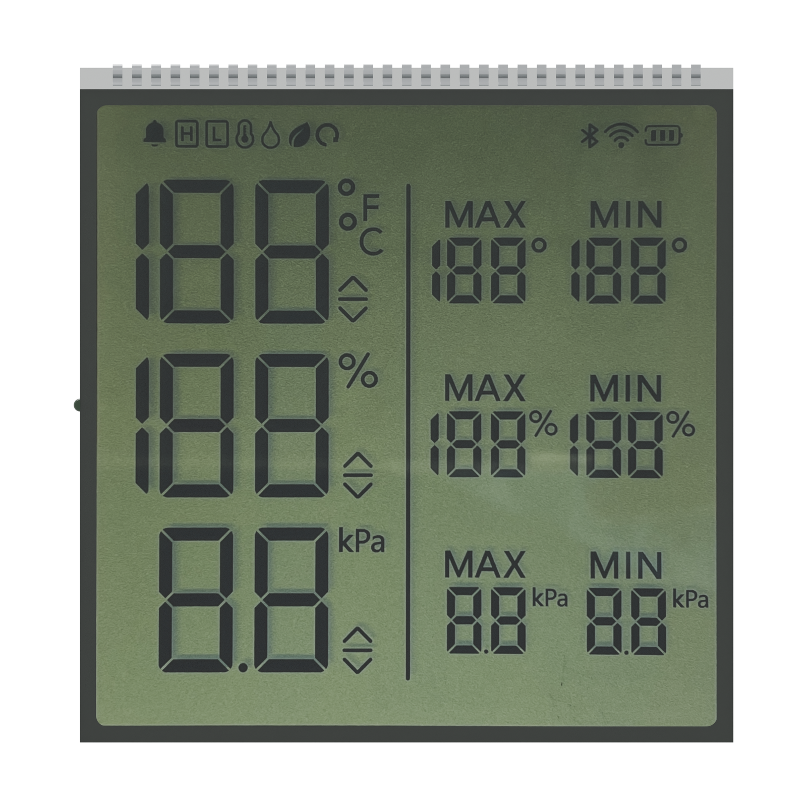
Front rendering of S3957D, showing the display artwork and glass outline. Materials and fine geometry are visual references for the OEM project.
OEM DISPLAY REFERENCE
S3957D is an HTN, positive-mode segmented LCD reference arranged in three horizontal measurement groups. Temperature, percent and kPa fields appear beside smaller MAX and MIN fields, with status icons along the top.
Images, 3D geometry and listed parameters are OEM reference information. Final dimensions, electrical requirements, optical configuration and construction are confirmed for your project.
Short product video. Playback starts when you press play.
01 / REFERENCE CONFIGURATION
A reference configuration for discussing your LCD project. Final specifications are subject to project confirmation.
| Model reference | S3957D |
|---|---|
| Rear glass width × height | 61.00 ± 0.20 × 63.00 ± 0.20 mm |
| Front glass width × height | 61.00 ± 0.20 × 61.00 ± 0.20 mm |
| Minimum viewing area | 58.00 × 58.00 mm |
| LCD thickness | 2.80 mm maximum |
| Glass thickness per layer | 1.10 ± 0.10 mm |
| Pin pitch | 1.80 mm |
| Display mode | HTN, positive |
| Connection | Pins |
| LCD operating voltage | 5.0 V |
| Drive condition | 1/8 duty, 1/4 bias |
| Frame frequency | 64 Hz |
| Viewing direction | 12 o’clock |
| Rear polarizer | Transflective, adhesive |
| Front polarizer | Transmissive, adhesive |
| Operating temperature | −20 °C to +70 °C |
| Storage temperature | −30 °C to +80 °C |
02 / OEM DESIGN
Bring your requirements. We will review the configuration with you.
Check the 58.00 × 58.00 mm minimum viewing area and the 61.00 × 63.00 mm rear glass outline against the enclosure.
Review the upper pin row at 1.80 mm pitch and reserve the required PCB contact and assembly clearance.
The drawing lists 1/8 duty and 1/4 bias at 5.0 V. Review the segment mapping for all three reading groups and their smaller limit fields.
03 / APPLICATION DIRECTION
Use this reference to plan a controller panel that presents several readings and their recorded limits. Confirm the meaning of each field, the units and the required MAX/MIN behavior in the product design.
04 / PRODUCT SUPPORT
The reference lists 5.0 V LCD operating voltage and 1/8 duty, 1/4 bias, at 64 Hz frame frequency. Check these requirements against your LCD driver; final electrical requirements are confirmed for the project.
The legends identify display fields. Pressure range, humidity range, measurement accuracy and the required sensors must be confirmed separately for the finished controller.
YOUR NEXT LCD PROJECT
Share your required display content, enclosure space, drive arrangement, operating environment and target quantity.


