
Automotive HUD TFT LCD Display Guide
The question usually arrives in a very practical form, not as a theory question: “We are building a car HUD. Can this TFT LCD work inside the PGU?”
The engineering review should first establish where the LCD sits in the optical path, how much light is lost before the image reaches the driver, how much heat the PGU can remove, and whether the interface and FPC can fit the mechanical layout. In an automotive HUD, the TFT-LCD is only the image source. The driver sees the result after that image has passed through the backlight, LCD stack, mirrors, windshield, and eye box.
That is why an automotive HUD TFT LCD should be reviewed as a system component, not as a normal dashboard screen. Size and resolution matter, but they are only the beginning. The real project risk is usually hidden in brightness planning, optical efficiency, backlight heat, polarizer durability, interface selection, FPC routing, and reliability testing.
What to Check First
- Where the TFT-LCD image is generated inside the PGU, and what optical parts sit after it.
- Whether the requested brightness is an LCD-level value or a driver-eye visibility target.
- How much heat the backlight creates, and whether the polarizer, films, LEDs, and frame can survive it.
- Whether the host interface, FPC direction, connector position, and PGU space limit match the module design.
- Whether the RFQ includes HUD optical targets, not just panel size, resolution, and a general “automotive grade” request.
A Practical Review Path
- Start with the HUD system, not the LCD part number
- Look at the PGU and projection path
- Review how TFT-LCD creates the source image
- Check the engineering items that often decide feasibility
- Prepare an RFQ that a display supplier can actually judge
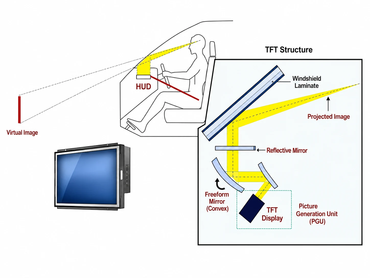
Start With the HUD System, Not the LCD Part Number
A typical head-up display has three important parts. The first is the PGU, or picture generation unit. This is where the display image is created. The second is the optical path, often including a reflective mirror and a freeform mirror. The third is the windshield or combiner, which reflects the projected image toward the driver’s eyes.
In the driver’s view, the image appears to float outside the windshield. That visual effect is not produced by the LCD alone. It is created by the entire HUD optical path. The TFT-LCD provides the source image, but the mirror geometry, windshield laminate, projection distance, and driver eye box decide how that image is finally perceived.
This is the first practical difference between a HUD display and a direct-view automotive display application. A center stack or cockpit screen can be evaluated directly by luminance, contrast, viewing angle, touch, cover glass, and mechanical fit. A HUD PGU display must be evaluated by what reaches the driver’s eyes after the optical path. If that distinction is missed at the RFQ stage, the project can look simple on paper and become difficult after the optical layout is fixed.
The PGU Is Where Many Display Problems Become System Problems
The projection diagram shows a structure with LCD panels, dichroic mirrors, a prism, lens, lamp, and projected image. The exact architecture can vary by HUD design, but the engineering lesson is consistent: the display image is transformed by the optical system before it becomes useful to the driver.
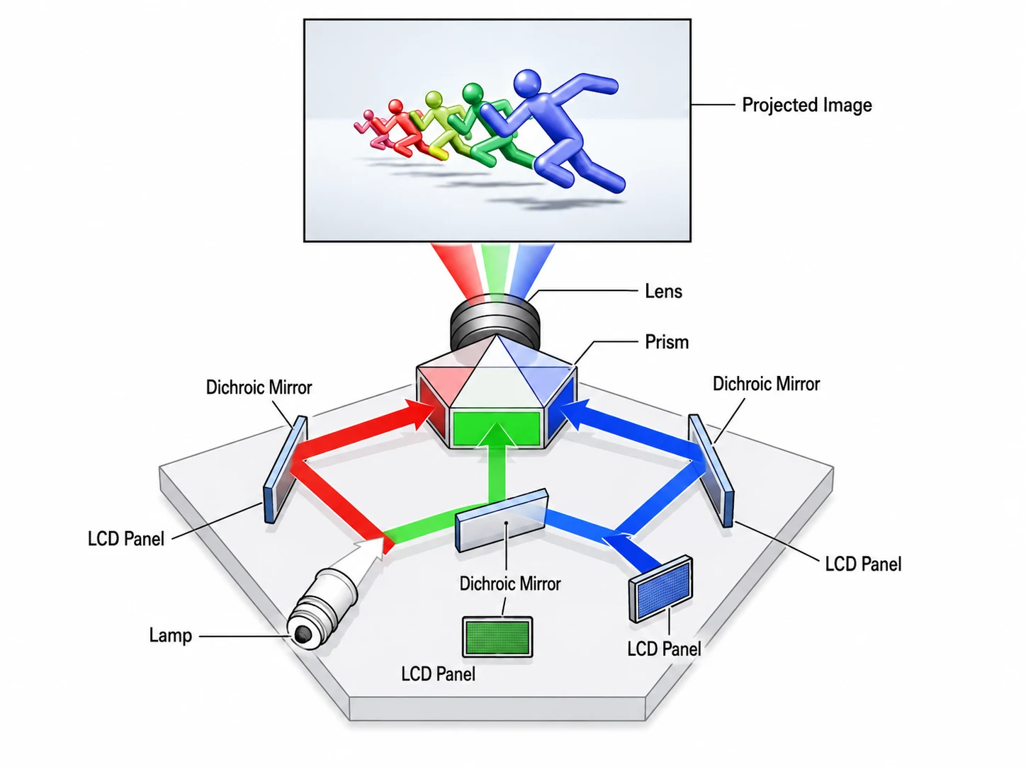
In many real RFQs, buyers mention only a target brightness such as “high brightness TFT LCD” or “sunlight readable display.” For HUD projects, this is not enough. Light is lost in the optical path, and more backlight power creates more heat inside the PGU. If the heat is not controlled, the display may pass a short demo but fail long-term stability, polarizer durability, LED lifetime, or appearance requirements.
This is also where a supplier conversation becomes more valuable than a simple catalog search. A catalog can tell you active area, resolution, interface, and outline size. It cannot tell you whether your mirror path, windshield reflection, PGU enclosure, and heat path will leave enough useful luminance for the driver.
That is why the display supplier should know the HUD type, optical path, brightness target at the driver’s eye if available, expected optical loss, operating temperature, and PGU space limit. If those details are still open, the RFQ should say so clearly. SuccessLCD can then review whether a standard or modified custom TFT LCD module is a reasonable starting point.
Why TFT-LCD Still Makes Sense as the Image Source
The core TFT-LCD principle is still the same as in other active-matrix display modules. A TFT array on the lower glass substrate controls each pixel. Liquid crystal material changes the light state. A color filter forms red, green, and blue sub-pixels. Polarizers and the backlight work together to create a visible full-color image.
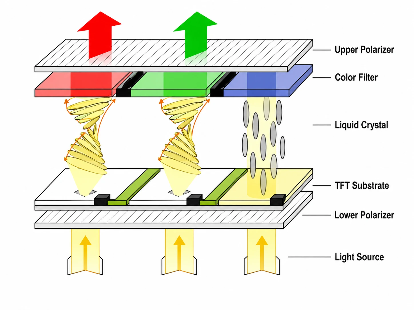
This structure gives TFT-LCD several practical advantages for HUD use. It can support sharp graphics, warning icons, navigation prompts, speed display, and color-coded information. The supply chain is mature, module sizes are flexible, and the cost-performance balance is often attractive for compact HUD and windshield HUD designs.
The same structure also explains the challenges. Because TFT-LCD depends on a backlight, heat is always part of the conversation. Because it uses polarizers and liquid crystal material, wide temperature and sunlight exposure must be checked carefully. Because the HUD image is projected rather than directly viewed, the display’s native brightness is only one part of the real visibility result.
What the Layer Stack Means for Sourcing
The fourth source image shows the cross-sectional structure of a TFT LCD. For a normal buyer, this may look like a layer diagram. For a HUD project, it is a reminder that many small material and assembly choices can affect the final display behavior: glass substrate, black matrix, polarizer, color filter, alignment layer, common electrode, liquid crystal, TFT, storage capacitor, pixel electrode, diffuser, prism sheet, reflector, light guide plate, and lamp or LED source.
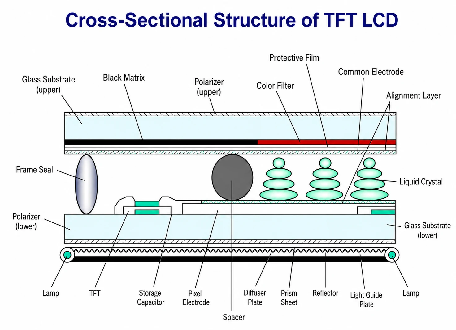
For display sourcing, this means the module should not be reduced to a part number too early. A HUD PGU may require custom backlight review, FPC direction changes, connector adjustments, tighter appearance criteria, or a different thermal path. The TFT LCD module manufacturing process explains how driver bonding, FPC attachment, backlight assembly, frame integration, and final testing turn the LCD cell into a usable module.
The Checks That Usually Decide Whether the Module Is Feasible
A practical HUD display review should connect optical design and module engineering. The table below is a better starting point than asking for a display only by size.
| Selection factor | Why it matters in HUD | What to confirm |
|---|---|---|
| Brightness and optical loss | The driver sees the reflected image after the optical path, not the LCD directly. | Backlight target, optical efficiency, expected loss, dimming method, sunlight readability. |
| Thermal design | High backlight power and sunlight load can stress the PGU and LCD materials. | Operating temperature, heat dissipation path, LED current, polarizer and film durability. |
| Resolution and active area | Speed, warning symbols, ADAS prompts, and navigation graphics must stay readable after projection. | Pixel matrix, active area, virtual image size, minimum icon or text size. |
| Interface and timing | The host processor must drive the display reliably without layout or EMI surprises. | RGB, LVDS, MIPI DSI, SPI, MCU, or eDP; frame rate; cable length; controller support. |
| Mechanical integration | PGU packaging often leaves little space for display thickness, FPC bend, and heat parts. | Outline drawing, FPC direction, connector position, bend radius, mounting method. |
| Reliability plan | Automotive electronics face heat, cold, vibration, humidity, and long lifecycle expectations. | Temperature range, vibration, ESD, aging, backlight lifetime, appearance standard. |
If the host interface has not been selected, compare RGB, LVDS, MIPI DSI, and SPI in the TFT LCD interface guide. Interface choice can change FPC pin count, PCB routing, EMI behavior, firmware workload, and long-term sourcing.
Where TFT-LCD Is Strong in a HUD Project
From a sourcing and engineering point of view, TFT-LCD remains attractive because it is mature, cost-efficient, full-color, and relatively easy to integrate. These advantages matter in real OEM/ODM projects where the buyer must balance performance, supply stability, packaging, and cost.
- Mature technology: TFT-LCD has a well-developed supply chain and proven module assembly path.
- High image detail: Active-matrix pixel control supports fine text, symbols, and graphics.
- Full-color display: Color filters enable navigation, warning, and ADAS UI colors.
- Integration flexibility: The module can be reviewed with custom FPC, connector, backlight, and frame requirements.
- Cost-performance balance: TFT-LCD can be a realistic option for compact HUD and cost-sensitive automotive display projects.
Design Risks to Review
Projection distance and high-temperature behavior require a system-level review. TFT-LCD is not automatically unsuitable for HUD, but the design must control optical distance, visibility, and heat from the beginning.
For compact HUD, a shorter virtual image distance may be acceptable. For AR-HUD, the system may need a larger image, wider field of view, and longer virtual distance. That can make the optical design much harder. At the same time, higher brightness increases thermal load. A display that works on the bench may not be stable inside a hot PGU without backlight, polarizer, and heat path review.
This is why a serious automotive HUD TFT LCD RFQ should include more than “high brightness” or “automotive grade.” It should describe the display target, PGU space, optical assumptions, thermal constraints, and reliability expectations.
What to Include in the RFQ
Before requesting a quote, prepare the following details. If some values are still unknown, mark them as open instead of leaving them out.
- HUD type: windshield HUD, combiner HUD, compact HUD, or AR-HUD concept.
- Display size, active area, resolution, and viewing direction.
- Virtual image size, virtual image distance, field of view, and eye box target if available.
- Brightness target at LCD level and any expected optical loss assumptions.
- Backlight voltage, current limit, dimming method, and heat dissipation path.
- Interface requirement: RGB, LVDS, MIPI DSI, SPI, MCU, eDP, or open to recommendation.
- FPC direction, connector type, connector pitch, pin count, and available bend radius.
- Operating temperature, storage temperature, sunlight exposure, vibration, ESD, and aging requirements.
- Expected annual quantity, project stage, sample schedule, and lifecycle target.
For a broader purchasing template, use the TFT LCD module RFQ checklist. It helps organize size, interface, brightness, touch or cover lens, mechanical, reliability, and lifecycle requirements before supplier review.
Need a TFT LCD Review for an Automotive HUD Project?
Send the target display size, resolution, interface, brightness target, FPC direction, PGU space limit, operating temperature, and any optical constraints you already know. SuccessLCD can help review whether a standard TFT LCD module, modified backlight, custom FPC, or deeper optical discussion is the better starting point.
Buyer Questions That Usually Decide the Project Direction
What is the role of TFT-LCD in an automotive HUD?
In a TFT-LCD HUD design, the display is usually part of the picture generation unit. It creates the source image, while the backlight, mirrors, windshield or combiner, and optical path enlarge and reflect that image so the driver sees a virtual display ahead of the vehicle.
Why is brightness difficult in HUD TFT LCD design?
The driver does not see the LCD directly. Light passes through the PGU optics and reflection path before reaching the eyes, so optical losses can be significant. Increasing backlight power may improve visibility, but it also raises heat and reliability risk.
Is TFT-LCD suitable for AR-HUD?
TFT-LCD can be considered for some HUD and compact PGU designs, but AR-HUD requirements are more demanding. Larger virtual image size, longer projection distance, wider field of view, and tighter thermal control may require deeper optical and system-level review.
What should I send before asking for a HUD TFT LCD quote?
Send the display size, resolution, interface, brightness target, PGU space limit, FPC direction, backlight electrical limits, optical assumptions, operating temperature, reliability test needs, expected quantity, and lifecycle target.
Conclusion
Automotive HUD TFT LCD technology is practical because it is mature, scalable, full-color, and cost-effective. But in a head-up display, the TFT-LCD is not just a screen. It is part of a PGU and optical system where brightness, heat, reflection, interface, FPC routing, and reliability all interact.
For a real project, start with the optical target and driver visibility requirement, then translate those requirements into a display module RFQ. That gives the supplier enough information to review the TFT LCD, backlight, FPC, interface, and reliability path before samples are built.
Need help choosing or customizing an LCD module?
Share your target size, interface, brightness, touch panel, cover lens, operating temperature and annual quantity. Our engineering team can review the requirements and suggest a practical TFT, mono LCD or custom display path.
- Review TFT, mono LCD, touch panel and optical bonding options.
- Check interface, backlight, FPC, lifecycle and reliability requirements.
- Prepare a clearer RFQ so the quotation is faster and more accurate.


