
Display opening
Check the 78.10 × 54.20 mm minimum viewing area and the 81.10 × 59.70 mm rear glass outline against the enclosure.
Navigate
Rotate, zoom and inspect the product. Loads on request.
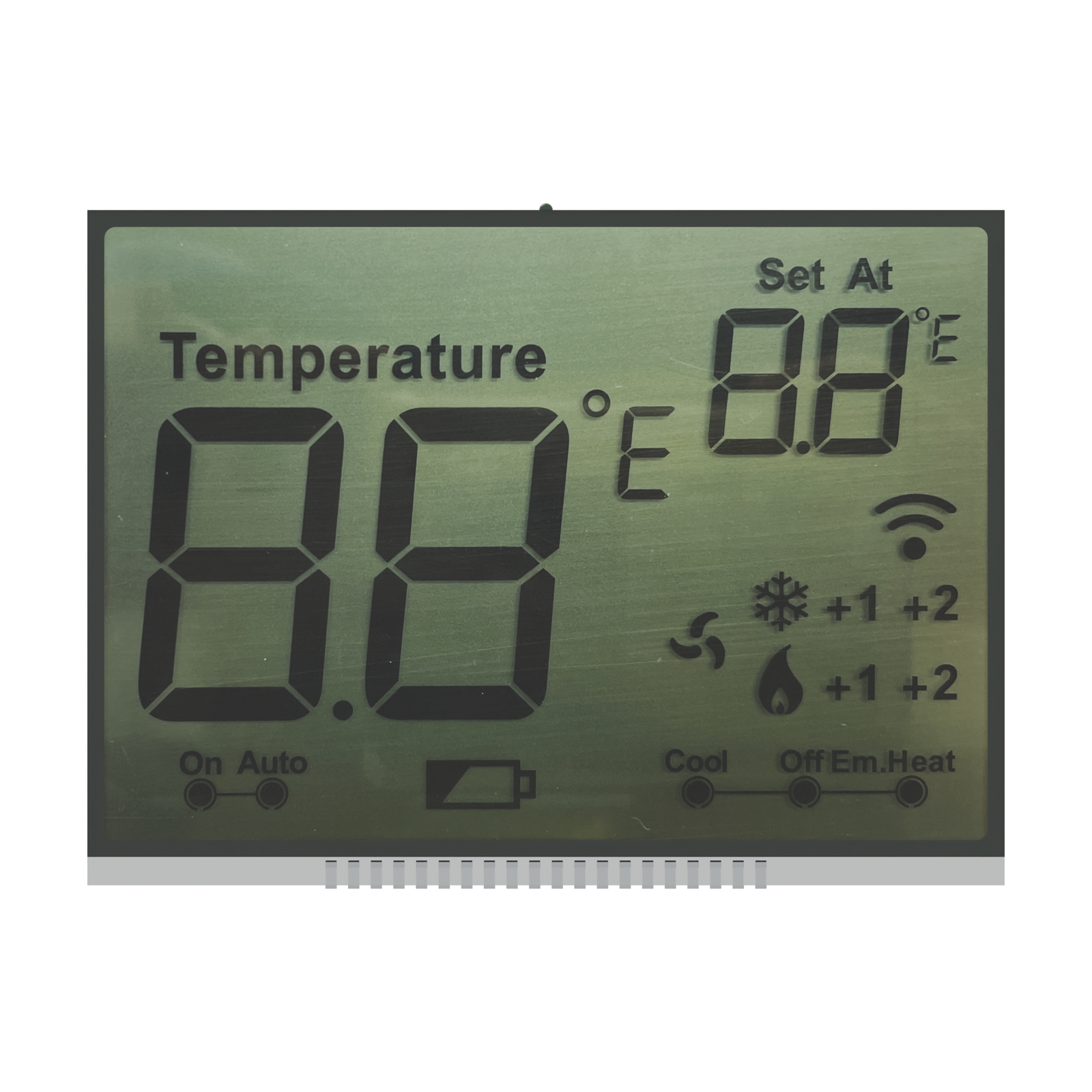
Front rendering of S3926D, showing the display artwork and glass outline. Materials and fine geometry are visual references for the OEM project.
OEM DISPLAY REFERENCE
S3926D is an HTN, positive-mode segmented LCD reference with a large temperature field and a smaller Set At field. Fan, heating, cooling, battery and status symbols occupy the right and lower portions of the display.
Images, 3D geometry and listed parameters are OEM reference information. Final dimensions, electrical requirements, optical configuration and construction are confirmed for your project.
Short product video. Playback starts when you press play.
01 / REFERENCE CONFIGURATION
A reference configuration for discussing your LCD project. Final specifications are subject to project confirmation.
| Model reference | S3926D |
|---|---|
| Rear glass width × height | 81.10 ± 0.20 × 59.70 ± 0.20 mm |
| Front glass width × height | 81.10 ± 0.20 × 57.20 ± 0.20 mm |
| Minimum viewing area | 78.10 × 54.20 mm |
| LCD thickness | 2.80 mm maximum |
| Glass thickness per layer | 1.10 ± 0.10 mm |
| Pin pitch | 2.00 mm |
| Display mode | HTN, positive |
| Connection | Pins |
| LCD operating voltage | 3.0 V |
| Drive condition | 1/4 duty, 1/3 bias |
| Frame frequency | 64 Hz |
| Viewing direction | 12 o’clock |
| Rear polarizer | Transflective, adhesive |
| Front polarizer | Transmissive, adhesive |
| Operating temperature | 0 °C to +50 °C |
| Storage temperature | −10 °C to +60 °C |
02 / OEM DESIGN
Bring your requirements. We will review the configuration with you.
Check the 78.10 × 54.20 mm minimum viewing area and the 81.10 × 59.70 mm rear glass outline against the enclosure.
Review the lower pin row at 2.00 mm pitch and map the temperature, setpoint and status segments to the LCD driver.
The rear polarizer is transflective and the viewing direction is 12 o’clock. Evaluate readability at the intended mounting height and illumination.
03 / APPLICATION DIRECTION
Use this reference to plan room-temperature, setpoint and operating-mode indications on a temperature-controller panel. Confirm the required units and heating or cooling stage symbols with the controller design.
04 / PRODUCT SUPPORT
The reference lists 3.0 V LCD operating voltage and 1/4 duty, 1/3 bias, at 64 Hz frame frequency. Check these requirements against your LCD driver; final electrical requirements are confirmed for the project.
Select the required stage, fan and mode symbols with the control logic. The presence of these segments does not define the controller’s supported equipment or sensing hardware.
YOUR NEXT LCD PROJECT
Share your required display content, enclosure space, drive arrangement, operating environment and target quantity.


