
LCD Backlight Module Guide: Structure, Edge-Lit vs Direct-Lit
Quick answer: An LCD backlight module uses LEDs, optical films and a light guide or direct-lit array to provide reliable, uniform light across a TFT LCD panel.
On this page
What an LCD backlight module does
A TFT LCD panel modulates light; it does not create its own visible image light. The backlight module supplies controlled illumination from behind the panel so the liquid-crystal layer and color filter can form a visible image. For an OEM product, the backlight affects luminance, uniformity, module thickness, power demand, thermal load and long-term brightness stability.
It should not be treated as a separate afterthought. The LED arrangement, optical films, mechanical frame and driver conditions have to fit the selected LCD panel, touch stack, enclosure and intended operating environment.
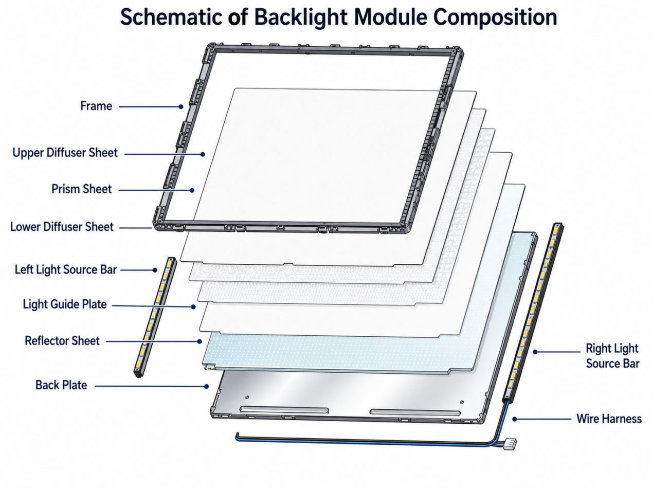
Core parts of a TFT LCD backlight module
LED light source and backlight driver
Modern LCD modules commonly use white LEDs. Their arrangement, drive current, dimming method and thermal path determine the usable luminance target and the stress placed on the backlight system. CCFL is mainly encountered in legacy equipment and replacement projects, where electrical and mechanical compatibility must be checked before any change is approved.
Light guide plate (LGP)
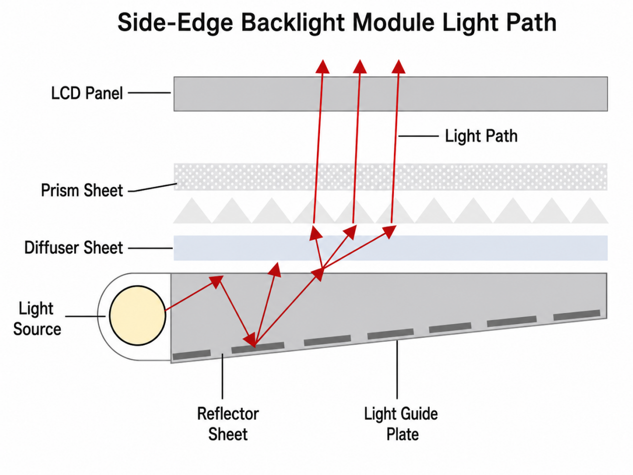
An LGP is central to most edge-lit structures. LEDs inject light from the side, and engineered dot patterns or microstructures extract that light across the panel area. The LGP thickness, dot pattern, LED position and reflector design all influence brightness uniformity.
Reflector, diffuser and brightness-enhancement films
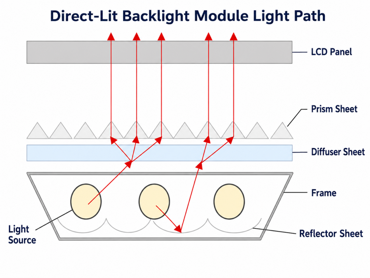
The reflector returns downward light toward the panel. Diffuser films help blend the light and reduce visible hot spots. Brightness-enhancement or prism films redirect part of the available light toward the preferred viewing direction. These films improve the optical result as a system; their exact stack depends on the panel, thickness allowance, brightness target and uniformity requirement.
For a broader process view, see our TFT LCD module manufacturing guide.
Edge-lit versus direct-lit backlights
The backlight architecture should match the product constraints. An edge-lit module is often chosen where a slim profile and lower mechanical depth are important. A direct-lit module places LEDs behind the panel area and can offer a different path for luminance distribution, but it typically needs more depth and careful diffuser spacing to avoid LED hot spots.
| Design factor | Edge-lit backlight | Direct-lit backlight |
|---|---|---|
| LED position | At one or more module edges | Behind the panel area |
| Optical element to review first | Light guide plate, dot pattern and edge coupling | LED pitch, diffusion distance and optical mixing |
| Mechanical implication | Often supports a thinner module profile | Usually needs more depth behind the LCD |
| Engineering risk to control | Edge-to-center uniformity and light-guide consistency | Hot spots, thermal distribution and diffuser spacing |
| Local-dimming note | Limited unless a specific zoned design is used | May support zoned control in purpose-designed backlight architectures |
Backlight checks before sample approval
A backlight should be checked with the complete module and enclosure, not only as a standalone LED specification. Review the following before a prototype or replacement is locked:
- Target luminance, uniformity tolerance and measurement conditions.
- LED current, dimming method, supply voltage and driver capability.
- Backlight power, ambient temperature, duty cycle and heat path into the enclosure.
- Light-guide, diffuser and prism-film stack against the required thickness.
- Brightness decay, replacement availability and lifecycle risk for long-running products.
How backlight design supports sunlight readability
Higher backlight luminance can improve visibility in bright environments, but it is only one part of the result. Cover-glass reflection, touch panel layers, anti-reflective or anti-glare treatment and optical bonding can also control perceived contrast. Read our TFT LCD sunlight readability guide for the full optical-stack decision path.
For projects that need outdoor or high-ambient-light performance, compare the backlight target with our high-brightness TFT LCD module options before committing to a final enclosure.
Frequently asked questions
Does every TFT LCD use a light guide plate?
No. A light guide plate is typical of edge-lit structures. Direct-lit modules distribute LEDs behind the panel and use a different optical mixing arrangement.
Can a brighter LED backlight solve outdoor readability by itself?
Not always. A higher luminance target helps, but surface reflection and internal air gaps can still reduce perceived contrast. The front stack and thermal design should be reviewed together with the backlight.
What causes uneven LCD backlight brightness?
Potential causes include LED output variation, LGP pattern issues, optical-film alignment, insufficient mixing distance, reflector defects, driver imbalance and heat-related changes. The cause should be confirmed using the final module structure rather than a single visual symptom.
Send a clearer LCD backlight RFQ
For a new module or a replacement review, send the size, resolution, interface, target brightness, operating temperature, dimming requirement, enclosure depth, application environment and expected quantity. You can review TFT LCD module paths, compare industrial HMI selection factors, or send an LCD RFQ for a practical engineering review.


