
Discontinued LCD replacement
How to Replace a Discontinued LCD Module Without Redesigning the PCB
When an LCD module becomes discontinued, the urgent question is not only “can we find the same size screen?” The real question is whether a replacement display can work with the existing PCB, connector, FPC route, firmware, enclosure, backlight and approval plan without creating a hidden redesign project.
This guide is written for OEM engineers, sourcing teams and product managers who need to replace an obsolete TFT LCD module, mono LCD, LCM or touch display while keeping production risk under control.
Quick Answer
To replace a discontinued LCD module with minimal PCB redesign, first document the original module baseline: outline size, active area, FPC direction, connector pitch, pin count, pinout, interface, voltage rails, backlight drive, touch path, cover lens, brightness and operating environment. Then classify the replacement path as drop-in, close-fit modification, custom display replacement or controlled product redesign.
In This Replacement Guide
When Should an OEM Start LCD Replacement Planning?
Start as soon as you receive a PCN, EOL notice, supply warning, repeated delay, quality change or last-time-buy request. Waiting until the final stock is nearly exhausted forces the team to accept a weak substitute, rush sample validation or redesign under pressure.
| Trigger | What it means | Recommended response |
|---|---|---|
| PCN | A material, process, driver IC, backlight, factory or specification detail may change. | Compare old and new drawings, electrical parameters, optical output and validation requirements. |
| ECN | A design or engineering detail has changed. | Check pinout, timing, connector, firmware and mechanical impact before approval. |
| EOL notice | The original module or key component will no longer be supplied after a defined point. | Start replacement sourcing, sample planning and last-time-buy analysis immediately. |
| Unstable supply | The supplier cannot confirm repeated delivery or lifecycle continuity. | Prepare a second source or controlled replacement path before production is blocked. |
Four Practical Paths for Discontinued LCD Replacement
Not every replacement project needs a full custom display. The right path depends on how much of the host PCB, enclosure, firmware and approval process can change.
| Path | When it fits | Main risk | Next step |
|---|---|---|---|
| Drop-in replacement | The original mechanical and electrical design can remain almost unchanged. | Small FPC, connector, firmware or backlight differences may still break compatibility. | Compare drawings and test with the real host board. |
| Close-fit modification | A near-match display can fit after minor FPC, connector or stack adjustment. | Tooling, cable routing, enclosure clearance or schedule may be affected. | Run drawing review before sample order. |
| Custom replacement | No standard module can satisfy the old outline, pinout or front-stack constraints. | Project cost, validation time, tooling and lifecycle planning need approval. | Prepare full old-module data and forecast context. |
| Controlled redesign | The old system cannot support a safe replacement route. | Firmware, PCB, certification and production timing become the main project risks. | Plan a redesign path instead of forcing an unsafe substitute. |
How to Avoid PCB Redesign Risk
Most OEM teams want to keep the host PCB unchanged. That is possible only when the replacement candidate matches the old electrical and mechanical assumptions closely enough, or when the difference can be handled by a controlled FPC or connector adaptation.
| Risk area | What to compare | Why it affects the PCB |
|---|---|---|
| Connector pitch and pin count | Pitch, pin number, mating side, lock type, height and footprint. | A different connector can require PCB layout changes or adapter FPC design. |
| Pinout and pin 1 direction | Signal order, power pins, backlight pins, reset and touch pins. | Wrong pin mapping can damage the module or make the display fail to initialize. |
| Interface type | SPI, MCU, RGB, LVDS, MIPI or another agreed interface. | The host processor and firmware must support the replacement interface. |
| Voltage rails | Logic voltage, analog rails, backlight voltage and current. | The existing power circuit may not support a different module load. |
| Initialization and timing | Driver IC, command sequence, timing table and firmware dependency. | A similar-looking module may require software changes. |
| FPC direction and length | Exit side, fold direction, stiffener, bend radius and cable path. | The display may not reach the existing connector or may collide with the enclosure. |
| Backlight control | LED series/parallel route, current, PWM dimming and thermal load. | Backlight differences can affect power design, brightness and heat. |
| Touch controller | RTP/CTP type, I2C/USB path, interrupt/reset pins and firmware support. | Touch integration may fail even when the LCD image works. |
For deeper interface planning, use the TFT LCD interface guide. For file intake before quotation, use the LCD drawing and specification review checklist.
Build an Old Module Baseline Before Searching for Replacements
The old module baseline is the control record for the replacement project. It helps the supplier decide whether a standard, modified or custom route is realistic.
Collect from the old module
- Front photo, back photo, FPC photo and label photo.
- Part number, supplier name and revision if visible.
- Old datasheet, drawing, purchase spec or approval record.
- Outline size, active area, viewing area and total thickness.
- FPC exit direction, connector type, pitch and pin count.
- Interface, pinout, voltage rails and backlight details.
Collect from the product
- Host-board connector photo and PCB constraints.
- Enclosure opening, bezel, mounting and cable route.
- Firmware or controller-board constraints.
- Brightness, touch, cover-lens or optical-bonding needs.
- Operating environment and approval requirements.
- Remaining stock, sample timing and target production schedule.
Replacement Compatibility Review Table
Use this table to avoid approving a replacement only because it has the same diagonal size. The goal is to classify each item as matched, adaptable, open or high risk.
| Review item | Matched | Adaptable | High-risk signal |
|---|---|---|---|
| Outline and active area | Same dimensions and viewing position. | Small bezel or housing adjustment possible. | Active area does not align with enclosure window. |
| FPC route | Same exit side, length and bend route. | Custom FPC may solve routing. | FPC exits on the wrong side or cannot reach the connector. |
| Connector | Same pitch, pin count, height and orientation. | Adapter FPC or connector change can be reviewed. | Host PCB is fixed and connector cannot change. |
| Pinout | Signal and power pins match. | Pin mapping can be changed by FPC design. | Power or backlight pins conflict with host board. |
| Interface | Same interface and timing route. | Firmware update or controller adjustment possible. | Host processor cannot support the candidate interface. |
| Backlight | Voltage, current and dimming method match. | Driver circuit can support the new route. | Power or thermal budget is not enough. |
| Touch | Same RTP/CTP type and controller path. | Touch firmware or controller route can be adjusted. | Touch cannot work through existing cover lens or firmware. |
| Optical performance | Brightness, viewing direction and reflection risk fit the product. | Cover lens, bonding or backlight can be reviewed. | User environment needs stronger optical performance than the candidate. |
| Approval risk | Validation plan is simple and controlled. | Limited requalification is acceptable. | Certification, customer approval or production timing cannot absorb the change. |
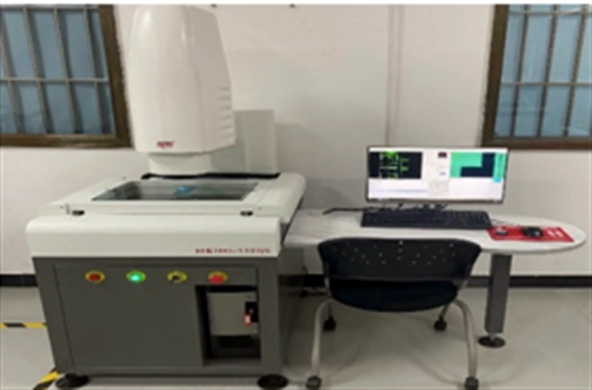
Sample Validation Sequence for Replacement LCD Modules
Replacement samples should be tested in stages. Do not approve a sample only because it turns on at the bench.

| Stage | What to test | Decision |
|---|---|---|
| 1. Document comparison | Old and new drawings, pinout, connector, voltage, interface and backlight. | Can a sample be ordered safely? |
| 2. Bench power-on | Basic display output, initialization, current draw and backlight behavior. | Does the module work electrically? |
| 3. Host-board test | Real PCB, firmware, connector, cable route and touch path. | Can it work in the actual system? |
| 4. Enclosure fit | Active area alignment, FPC bend, connector clearance and front stack. | Can the product be assembled? |
| 5. Optical review | Brightness, viewing direction, reflection, touch behavior and UI readability. | Does the user experience remain acceptable? |
| 6. Reliability screening | Aging, thermal, vibration or environmental checks according to project risk. | Is the replacement stable enough for the next build? |
| 7. Production handoff | Approved drawings, revision record, inspection criteria and change-control expectations. | Can purchasing and production control the new route? |
For the physical sample stage, use the LCD module sample validation checklist.
What to Send for a Faster Replacement LCD RFQ
A replacement RFQ should make the old constraints visible. The more complete the initial package is, the faster SuccessLCD can judge whether the route is standard, modified, custom or redesign-oriented.
| Send this | Why it helps | If unavailable |
|---|---|---|
| Old module part number and label photo | Identifies the original module family and revision clues. | Send clear front, back and FPC photos. |
| Old datasheet or drawing | Allows outline, active area, pinout, voltage and backlight comparison. | Send measured dimensions and visible connector details. |
| Host-board connector photo | Shows PCB constraints and mating direction. | State whether the PCB is fixed or can be modified. |
| Interface and firmware notes | Clarifies SPI, MCU, RGB, LVDS, MIPI or other host route. | Share controller IC or processor information if known. |
| Enclosure and cable route photos | Shows whether FPC direction and thickness are fixed. | Provide a sketch or marked photo. |
| Application environment | Explains brightness, temperature, touch and cover-lens needs. | Describe indoor, outdoor, vehicle, handheld or industrial use. |
| Quantity and timing | Separates urgent replacement, pilot build and long-term production planning. | Provide sample needs and estimated annual demand if known. |
Copy this short inquiry
Hello SuccessLCD team, we need to replace a discontinued LCD module used in [application]. The existing PCB/enclosure is [fixed / can be adjusted]. Available supporting files: [list the module photos, FPC/connector photos, drawings or datasheets you can provide]. Please review whether a standard, modified or custom replacement route is practical, and advise what information is still needed for sample planning.
How SuccessLCD Reviews a Discontinued LCD Replacement Project
SuccessLCD reviews replacement projects by comparing the old module baseline with the real product constraints. Depending on the project, the review may cover TFT LCD modules, mono LCD or LCM options, RTP/CTP touch panels, cover lens, AG/AR/AF requirements, air bonding, optical bonding and interface routes such as SPI, RGB, LVDS and MIPI.
What we can review from files
- Old module photos, label, FPC and connector details.
- Drawing, active area, outline and thickness constraints.
- Interface, pinout, voltage and backlight route.
- Touch, cover lens, bonding and optical requirements.
- Sample quantity, estimated demand and target schedule.
What still needs project confirmation
- Whether the host PCB can change.
- Whether firmware can be adjusted.
- Which dimensions are absolutely fixed.
- Which customer or regulatory approvals may be affected.
- Whether a last-time-buy bridge stock is needed.
If you are still preparing the first inquiry, use what to include in a TFT LCD module RFQ to structure the project details, then submit the known project requirements through the Contact page. Email available drawings or photos to sales@successlcd.com with your company and project reference.
Engineering approval gate · Reviewed 12 August 2026
Replacement Approval Gate: What Must Be Closed Before Pilot Build
Decision rule: a candidate replacement should move to pilot build only after every material difference has a controlled status, an owner and a verification action. Matching diagonal size, resolution or interface name is not approval evidence. The decision must connect the original module baseline, candidate drawing, host electronics, enclosure, firmware, optical stack and production controls.
Quick answer: close five gates before pilot build: source identity and revision, mechanical fit, electrical and firmware compatibility, optical and environmental suitability, and production/change control. A gate may be matched or deliberately adapted, but it must not remain unexplained. Any power-pin conflict, unsupported interface, uncontrolled FPC route or missing approval criterion is a stop condition.
| Approval gate | Minimum evidence | Release condition | Stop condition |
|---|---|---|---|
| 1. Source identity and revision | Original and candidate part numbers, supplier, revision, dated drawing or datasheet, and available PCN/EOL record. | Both configurations are traceable and the comparison uses controlled revisions. | Unknown revision, unverified cross-reference or no evidence that the quoted part matches the sample. |
| 2. Mechanical and front stack | Outline, active/view area, thickness, mounting, FPC exit and bend route, connector position, touch and cover-lens stack. | The sample can be assembled without uncontrolled stress, interference or viewing-window misalignment. | FPC cannot reach the fixed connector, active area misses the opening or stack height is unresolved. |
| 3. Electrical and firmware | Full pin map, voltage rails, power sequence, interface timing, backlight load, driver/controller identity, initialization and touch path. | Host-board and firmware compatibility are confirmed, or each required adaptation is defined and owned. | Power/ground conflict, unsupported signaling, unknown initialization or backlight load outside the existing design basis. |
| 4. Optical and environment | Brightness, viewing direction, contrast expectations, surface treatment, bonding, touch behavior, operating/storage environment and application-specific criteria. | Acceptance criteria are defined and the candidate is reviewed in the real enclosure and use condition. | Bench power-on is treated as optical or environmental approval. |
| 5. Production and change control | Approved drawing, sample/reliability plan, inspection criteria, revision record, packaging/label requirements and notification expectations. | Purchasing, engineering, quality and production share the same released configuration and decision record. | The sample is accepted without an approved revision, inspection basis or production handoff owner. |
Use four controlled statuses for every comparison item
- Matched: evidence shows the original requirement and candidate configuration align.
- Adaptable: a defined FPC, connector, firmware, backlight, touch or mechanical change can close the gap.
- Open: evidence is missing or the acceptance method has not been agreed; the item remains on hold.
- Stop: the candidate conflicts with a fixed safety, electrical, mechanical, firmware or approval constraint.
Minimum replacement decision record
- Original module identity and revision.
- Candidate module identity and revision.
- Host PCB and firmware version.
- Enclosure and front-stack revision.
- Comparison owner and review date.
- Status for every material difference.
- Required sample tests and acceptance criteria.
- Final decision, approver and released drawing.
Primary technical references
IEC 62402:2019, Obsolescence management, provides lifecycle-level requirements and guidance for establishing an obsolescence-management policy, plan, resolution process and performance review. For display integration, the Texas Instruments TIDA-010013 reference design demonstrates that a change in LCD resolution/interface can require specific pixel timing, signal mapping, FFC connection and backlight decisions. Microchip’s AVR32114 LCD controller application note is an additional example of controller-to-display integration being an electrical and software task rather than a size-only substitution.
Use the industrial LCD replacement solution page when you are ready for a feasibility review. Submit the original part number, host-board constraints, quantity and target schedule through the replacement RFQ route below. Email the original datasheet or drawing and clear front/back/FPC/connector photos to sales@successlcd.com with your company and project reference.
Evidence boundary: these references support the review method; they do not certify a specific replacement module. Drop-in compatibility, life-cycle continuity, timing, qualification, performance, cost and schedule remain project-specific and must be confirmed in controlled drawings, test records and the final quotation.
FAQ
Can a discontinued LCD module be replaced without changing the PCB?
Sometimes. It depends on connector pitch, pin count, pinout, interface timing, voltage rails, backlight drive, FPC direction and firmware support. A same-size display is not enough to guarantee PCB compatibility.
What should I check first when an LCD module is EOL?
Collect the old part number, datasheet, drawing, FPC photo, connector photo, pinout, backlight details, host-board constraints, enclosure limits and application requirements before choosing a substitute.
When is a custom LCD replacement needed?
A custom route may be needed when the old module has a fixed outline, special FPC direction, unique pinout, uncommon segment pattern, special touch stack or strict enclosure constraint that standard modules cannot meet.
Is a last-time buy enough to solve an EOL problem?
A last-time buy can buy time, but it does not solve long-term supply risk. Use the time to validate a replacement route, prepare drawings, test samples and control the production transition.
Why do replacement samples fail even when the screen turns on?
The sample may turn on at the bench but fail in the final product because of FPC routing, connector height, firmware initialization, backlight power, touch behavior, active-area alignment or enclosure interference.
What files help SuccessLCD review a replacement project faster?
Useful files include old module photos, label photos, FPC and connector photos, drawings, datasheets, host-board photos, interface notes, enclosure constraints, quantity estimate and target schedule.
Need a Discontinued LCD Replacement Review?
Send the old LCD module photos, label, FPC, connector, drawing, datasheet, host-board constraints and target quantity. SuccessLCD can help review whether the project fits a standard, modified, custom or redesign path.
- For urgent production risk, include remaining stock and target sample date.
- For fixed PCB projects, include connector and pinout information first.
- For fixed enclosure projects, include outline, active area and FPC route photos.
Related Resources
Technical Reference Note
This guide organizes common engineering and sourcing checks for discontinued LCD replacement projects. Final compatibility should be confirmed against the actual LCD module, host board, firmware, enclosure, optical stack, operating environment and customer approval plan.


