
ILI9341 vs ST7789 vs ILI9488: SPI TFT Driver ICs Compared
Quick answer: ILI9341, ST7789 and ILI9488 are TFT driver ICs with built-in frame memory, so a microcontroller can draw on them over SPI without its own display controller. ILI9341 and ST7789 both address up to 240 × 320 pixels; ST7789 is also the usual choice for small square and round 240 × 240 panels. ILI9488 drives 320 × 480 panels, but over 4-wire SPI it accepts 18-bit pixels only, so a full screen is three times larger than a 240 × 320 screen in 16-bit color.
The three share the standard drawing commands, so drawing code is similar, but their power and gamma setup differs. A module is not interchangeable just because the driver name matches; the initialization sequence must match the actual panel.
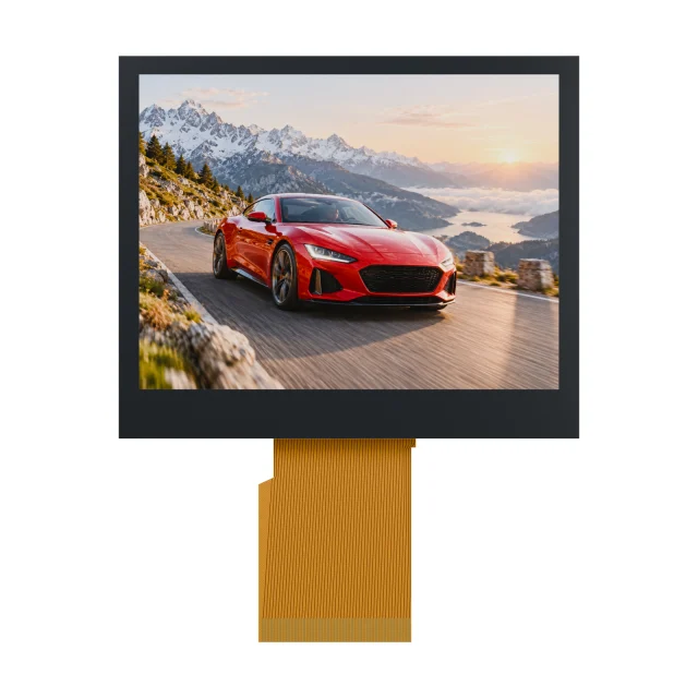
Side-By-Side Comparison
| ILI9341-type | ST7789-type | ILI9488-type | |
|---|---|---|---|
| Maker | Ilitek | Sitronix | Ilitek |
| Maximum resolution | 240 × 320 | 240 × 320 | 320 × 480 |
| Common panels | 2.2- to 3.2-inch 240 × 320 | 1.3- to 2-inch 240 × 240, 240 × 280, 170 × 320 and 135 × 240; 2- to 2.8-inch 240 × 320 | 3.5-inch 320 × 480 |
| Pixel formats over 4-wire SPI | 16-bit RGB565 or 18-bit RGB666 | 12-, 16- or 18-bit | 18-bit (3 bytes per pixel) or 3-bit; no 16-bit |
| Other host interfaces | 8- to 18-bit parallel, RGB | 8- to 18-bit parallel, RGB, 2-data-lane SPI | Parallel MCU, RGB |
| Full screen over SPI | 153,600 bytes | 153,600 bytes at 240 × 320; 115,200 at 240 × 240 | 460,800 bytes |
| Full screen at a 40 MHz SPI clock (data only) | about 31 ms | about 31 ms; about 23 ms at 240 × 240 | about 92 ms |
The 40 MHz figure is for comparison only. The ILI9341 datasheet specifies a minimum serial write cycle of 100 ns, which is 10 MHz; at that clock a full ILI9341 screen takes about 123 ms. Many designs run faster than the datasheet figure, which should be validated on the actual module, cable and temperature range. Check the serial timing in the datasheet of the exact variant, such as ST7789V, ST7789VW or ST7789V3.
What Limits Refresh Speed
- Bytes per pixel: 16-bit color sends 2 bytes per pixel; ILI9488 over SPI sends 3.
- SPI clock and wiring: long jumper wires and connectors limit the clock long before the controller does.
- Partial updates: set a window with the column and row address commands and send only the changed area. A 60 × 30 pixel value field is 3,600 bytes in 16-bit color.
- DMA: let the microcontroller’s DMA feed the SPI so the processor can prepare the next area.
- Tearing: the controllers provide a tearing-effect (TE) output; starting a full-screen write on TE avoids visible tearing.
When full-screen animation is needed, an 8- or 16-bit parallel bus, or a panel driven over RGB, is faster than SPI. The trade-offs are explained in I2C vs SPI vs UART vs parallel LCD interfaces.
Shared Commands And Initialization Differences
All three use the standard display command set for drawing:
| Command | Hex | Use |
|---|---|---|
| Software reset | 0x01 | Resets the controller registers |
| Sleep out | 0x11 | Wakes the controller; wait before the next command |
| Display inversion off / on | 0x20 / 0x21 | Many IPS panels need inversion on for correct colors |
| Display on | 0x29 | Turns the panel output on |
| Column / row address set | 0x2A / 0x2B | Defines the drawing window |
| Memory write | 0x2C | Starts pixel data for the window |
| Memory access control (MADCTL) | 0x36 | Rotation, mirroring and RGB or BGR order |
| Pixel format (COLMOD) | 0x3A | 0x55 for 16-bit, 0x66 for 18-bit |
The power, VCOM, gamma and panel timing registers are specific to each controller and each panel. That part of the initialization sequence should come from the module supplier, not from a library written for a different panel.
Common Problems When Bringing Up A Small TFT
| Symptom | Likely cause | Fix |
|---|---|---|
| Red and blue swapped | RGB/BGR bit in MADCTL | Toggle the BGR bit |
| Colors look like a negative | Inversion setting does not suit the panel | Switch between 0x20 and 0x21 |
| Image shifted, or a noisy strip at one edge | Panel smaller than the frame memory, such as 240 × 240 on a 240 × 320 controller | Add the column or row offset for the chosen rotation |
| Wrong orientation or mirrored | MADCTL rotation bits | Set rotation and mirroring together, then adjust offsets |
| ILI9488 shows wrong colors over SPI | Sending 16-bit pixels | Set 18-bit format and send 3 bytes per pixel |
| White screen with backlight on | No reset or incomplete initialization, wrong interface mode pins | Check reset timing, IM pins and the init sequence; see TFT white screen after power-on |
Which Driver For Which Product
- Wearables, round dials and small status screens: ST7789-type panels at 240 × 240 or similar. See round TFT LCD displays.
- 2.4- to 3.2-inch menus with SPI: ILI9341-type or ST7789-type 240 × 320 panels; use an 8-bit parallel version if the screen changes a lot.
- 3.5-inch 320 × 480: ILI9488-type over SPI works for mostly static screens; for animation, use parallel or RGB, or consider a 320 × 240 panel.
- Long production life: the driver IC can change between panel revisions. Ask for change notification and keep the initialization sequence under version control; see the discontinued LCD replacement guide.
Small TFT References In The SuccessLCD Catalogue
| Reference | Size and resolution | Published interface |
|---|---|---|
| S130MH2ZG-03 | 1.3-inch round, 240 × 240 | SPI / RGB / MCU |
| S177MEHS-04 | 1.77-inch portrait, 128 × 160 | SPI |
| S240MCQS-18P | 2.4-inch, 240 × 320, resistive touch | 8-bit MCU |
| S350MLQZ | 3.5-inch, 320 × 240 | SPI + RGB |
The driver IC and initialization code for each reference are confirmed from its module specification. On modules listed as “SPI + RGB”, SPI usually configures the driver and RGB carries the pixel data; check the specification. For more sizes, see the small TFT LCD display comparison and LCD controller and driver ICs.
ILI9341 vs ST7789 vs ILI9488 FAQs
What is the difference between ILI9341 and ST7789?
Both are TFT driver ICs with built-in frame memory for up to 240 × 320 pixels, with SPI, parallel and RGB interfaces. ILI9341 is typical of 2.2- to 3.2-inch 240 × 320 panels; ST7789 is also common on small 240 × 240, 240 × 280 and round panels. Their power and gamma setup commands differ.
Can I use ILI9341 code for an ST7789 display?
The drawing commands are the same standard commands, so drawing code carries over, but the initialization sequence, inversion setting and memory offsets must match the ST7789 panel. Use the module supplier’s initialization code.
Why is my ILI9488 display slow over SPI?
Over 4-wire SPI the ILI9488 accepts 18-bit pixels only, sent as 3 bytes, so a 320 × 480 screen is 460,800 bytes, about 92 ms at a 40 MHz clock. Update only changed areas, or use a parallel or RGB interface.
What SPI clock can an ILI9341 run at?
The datasheet specifies a 100 ns minimum write cycle, which is 10 MHz. Many designs run faster for writes; validate any higher clock on the actual module, cable and temperature range. Reads are slower.
Why are the colors on my TFT inverted or swapped?
Inverted colors usually mean the display inversion setting (0x20 or 0x21) does not suit the panel; swapped red and blue mean the RGB/BGR bit in the memory access control register is wrong.
Choosing a small TFT for an SPI host? Send the size, resolution, host processor, interface, update rate and viewing needs. Send your requirements for an engineering review, or browse TFT LCD modules. For a different outline or FPC, see custom TFT display engineering.