
UART Serial LCD Displays and Baud Rate: Speed, Wiring and Troubleshooting
Quick answer: A UART serial LCD takes commands and text over two signal wires, TX and RX, plus ground. Both ends must agree on the baud rate and frame format, most often 8 data bits, no parity and one stop bit (8N1). With 8N1 each byte costs 10 bits, so the usable rate is the baud rate divided by 10: 960 bytes per second at 9,600 baud and 11,520 bytes per second at 115,200 baud.
That is plenty for text and short commands, but far too slow to stream pixels: one 320 × 240 frame in 16-bit color takes more than 13 seconds at 115,200 baud. UART displays therefore either show text, or are “smart” modules that store images and fonts and draw them on command.
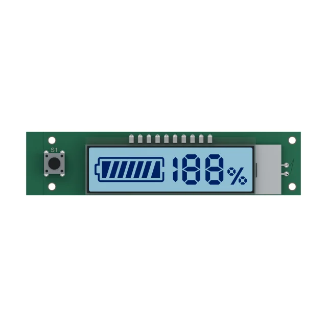
Types Of UART Serial Displays
| Type | What the host sends | Good for | Watch out for |
|---|---|---|---|
| Character LCD with a serial adapter | Text and a few control codes; the adapter drives an HD44780-type parallel bus | Status lines and simple menus with few host pins | The adapter’s own command set and its busy time after clear or home |
| Smart serial TFT (HMI module) | Commands such as “show page 3” or “set value 25”; images and fonts are stored in the module | Color user interfaces from small microcontrollers | Proprietary protocol and design software; lifecycle of the module, not just the panel |
| TFT module with a separate controller board | Commands to the board, which drives the panel over RGB, LVDS or MIPI | Larger displays in products whose host has only a serial port | Two parts to qualify and keep in supply |
For a comparison of UART with I2C, SPI and parallel buses, see I2C vs SPI vs UART vs parallel LCD interfaces. If the host can drive SPI or parallel directly, a plain character LCD module or a small TFT is usually simpler and faster.
Baud Rate And Update Time
The table assumes 8N1 framing and no gaps between bytes. Real protocols add headers, checksums and acknowledgements, so allow some margin.
| Baud rate | Bytes per second (8N1) | Rewrite a 16×2 screen (about 34 bytes) | One 320 × 240 frame, 16-bit (153,600 bytes) |
|---|---|---|---|
| 9,600 | 960 | about 35 ms | 160 s |
| 19,200 | 1,920 | about 18 ms | 80 s |
| 38,400 | 3,840 | about 9 ms | 40 s |
| 57,600 | 5,760 | about 6 ms | about 27 s |
| 115,200 | 11,520 | about 3 ms | about 13 s |
| 230,400 | 23,040 | about 1.5 ms | about 6.7 s |
| 921,600 | 92,160 | about 0.4 ms | about 1.7 s |
Adding a parity bit or a second stop bit makes each byte 11 bits, which cuts throughput by about 9 percent. For text displays, 9,600 or 19,200 baud is usually enough. Smart TFT modules commonly run at 115,200 baud or faster so that page changes and value updates feel immediate.
Baud Rate Error And Crystal Choice
A UART has no shared clock. The receiver times each bit from the start bit, so both ends must run close to the same rate. By the stop bit of an 8N1 frame, the accumulated timing difference must stay below about half a bit, which puts the theoretical limit near 5 percent of combined error. In practice, keep each side within about 2 percent.
The error comes from dividing the processor clock. A 16 MHz clock with 16× oversampling cannot make 115,200 baud exactly: the nearest divider gives about 111,111 baud, an error of −3.5 percent. Using 8× oversampling on the same clock gives about +2.1 percent. A UART crystal such as 11.0592 MHz or 14.7456 MHz divides exactly into the standard rates. If a display works at 9,600 baud but fails at 115,200, check the actual divider error on both ends first.
TTL, RS-232 And RS-485 Wiring
| Level | Signals | Distance | Notes |
|---|---|---|---|
| TTL / CMOS UART | 0 V and 3.3 V or 5 V, idle high | Inside one product or a short cable | Check that a 3.3 V input tolerates a 5 V output, or add a level shifter |
| RS-232 | Roughly ±3 V to ±15 V, inverted logic | Up to about 15 m at lower baud rates | Needs a transceiver; never connect RS-232 directly to microcontroller pins |
| RS-485 | Differential pair, several devices on one bus | Up to about 1,200 m at low data rates | Half-duplex wiring needs direction control; terminate long lines |
Cross the data lines: host TX to display RX and host RX to display TX, and always connect ground. On a long cable to a panel-mounted display, RS-485 or RS-232 is more robust than a TTL UART, and the cable also needs attention for ESD; see LCD ESD protection.
Designing A Reliable Display Protocol
- Frame every command: a start byte, a length, the command, the data and a checksum or CRC let the display reject corrupted messages.
- Respect busy time: clearing a character LCD or loading a page on a smart module takes time. Wait for an acknowledgement, use RTS/CTS flow control or follow the module’s documented delays.
- Send only what changed: update a value field, not the whole screen.
- Plan for recovery: if the baud rate can be changed by command, keep a documented way back to the default, such as a fixed rate at power-up.
- Test at temperature: oscillator drift on both ends adds to the divider error.
Troubleshooting A Serial LCD
| Symptom | Likely cause | Check |
|---|---|---|
| Random characters or symbols | Baud rate, data bits or parity mismatch; inverted RS-232 signal on a TTL input | Settings on both ends; signal level with a scope |
| Nothing appears | TX and RX not crossed, no common ground, wrong default baud rate | Wiring, ground, the module’s power-up rate |
| Mostly correct, occasional wrong characters | Clock error near the limit, noise on a long cable | Divider error, cable route and grounding |
| Characters lost in bursts | Display busy or its buffer full | Acknowledgements, flow control, delays after clear |
| Works on the bench, fails in the enclosure | Noise or ESD coupling into the cable | Cable route, ground return, RS-485 for longer runs |
For display faults that are not related to the serial link, see common LCD display problems.
UART Serial LCD FAQs
What baud rate should I use for a serial LCD?
Use the highest rate both ends support with low clock error. Text displays commonly use 9,600 or 19,200 baud; smart TFT modules commonly use 115,200 baud or more. Check the module’s default rate and how to restore it.
How many bytes per second does 115200 baud carry?
With 8 data bits, no parity and one stop bit, each byte takes 10 bits, so 115,200 baud carries 11,520 bytes per second before protocol overhead.
Why does my serial LCD show random characters?
Usually the baud rate or frame format does not match, or an RS-232 signal is connected to a TTL input, which inverts and over-drives the data. Check the settings on both ends and the signal levels.
Can I connect RS-232 directly to a microcontroller?
No. RS-232 uses inverted levels of roughly ±3 V to ±15 V, which can damage microcontroller pins. Use an RS-232 transceiver between the cable and the UART.
Is UART fast enough for a TFT display?
Not for streaming pixels: a 320 × 240 frame in 16-bit color is 153,600 bytes, about 13 seconds at 115,200 baud. UART TFT modules store images and fonts locally and draw them on command; for direct pixel updates use SPI, parallel or RGB.
Choosing a display for a serial host? Send the host processor, available interfaces, baud rate, cable length and screen content. Send your requirements for an engineering review, or compare TFT LCD modules and monochrome LCDs. For a custom serial display, see custom TFT display options.