
Window and lighting
Coordinate the 37.00 × 45.00 mm minimum viewing area with the housing window and lighting system. The colored segment appearance in renderings is a visual reference.
Navigate
Rotate, zoom and inspect the product. Loads on request.
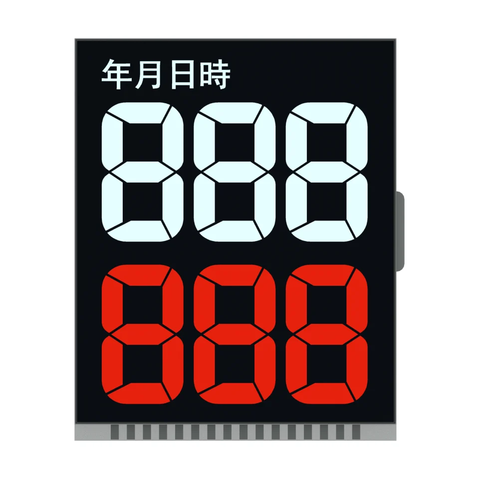
Front product rendering of S2287D, showing the two rows of large digits and fixed Chinese calendar legends on a white background.
OEM DISPLAY REFERENCE
S2287D stacks two rows of three large seven-segment digits below fixed Chinese calendar legends. The reference has a 37.00 × 45.00 mm minimum viewing area and a negative transmissive optical mode.
Images, 3D geometry and listed parameters are OEM reference information. Final dimensions, electrical requirements, optical configuration and construction are confirmed for your project.
Short product video. Playback starts when you press play.
01 / REFERENCE CONFIGURATION
A reference configuration for discussing your LCD project. Final specifications are subject to project confirmation.
| Model reference | S2287D |
|---|---|
| Glass outline | 40.00 ± 0.20 × 50.00 ± 0.20 mm |
| Front glass height | 48.00 ± 0.20 mm |
| Minimum viewing area | 37.00 × 45.00 mm |
| Maximum LCD thickness | 2.80 mm max |
| Display mode | Negative, transmissive |
| Drive condition | 1/4 duty, 1/3 bias |
| Viewing direction | 6 o'clock |
02 / OEM DESIGN
Bring your requirements. We will review the configuration with you.
Coordinate the 37.00 × 45.00 mm minimum viewing area with the housing window and lighting system. The colored segment appearance in renderings is a visual reference.
Confirm the electrical drive voltage, temperature limits and contact construction for the quoted revision before circuit design.
03 / APPLICATION DIRECTION
The source application is calendar displays. The year, month, day and time legends are fixed artwork; calendar calculations, timekeeping, control electronics and lighting are defined by the finished product.
ENGINEERING NOTES
How S2287D relates to LCD mode, drive, connection and integration choices, with links to the SuccessLCD engineering guides.
4 common electrodes share the segment lines. Set the controller to the duty, bias, voltage and frame frequency on the drawing. Duty and bias explained →
A negative LCD needs a backlight; the look is close to a VFD or LED readout. VFD vs LCD →
Digit, decimal point and icon layout set the segment count and pin map. 7-segment digit design →
04 / PRODUCT SUPPORT
This reference describes the LCD artwork and mechanical/optical information. A real-time clock, calendar logic and control electronics are not specified as included.
The drawing gives a 1/4 duty, 1/3 bias drive condition. Operating voltage and temperature limits are confirmed for the quoted project revision.
YOUR NEXT LCD PROJECT
Share your required display content, enclosure space, drive arrangement, operating environment and target quantity.


