
Camera Banding or LCD Flicker? What a Phone Video Can—and Cannot—Tell You
A field team sends a phone video. Dark bands roll slowly across an LCD, and the message says “screen flickering, please replace.” The person who filmed it may add that the screen looked normal in the room. Before rejecting the module or approving a replacement, it helps to be precise about what the video has shown.
It shows changing bands in the recorded screen area under those capture conditions. It does not yet establish whether they came from temporal light modulation, spatial sampling, or another imaging effect, or whether the display is damaged. Nor would a clip without bands show that the display is flicker-free. A single recording cannot settle these questions.
Why a camera can draw bands that the eye does not see
The explanation below concerns banding caused by changing light interacting with exposure timing; not every stripe in a screen photograph has that cause.
Many cameras do not capture a whole frame in one instant. With a rolling shutter, each row of the sensor starts and stops its exposure at a slightly different time, one line after another (Teledyne Vision Solutions). If the light reaching the sensor rises and falls during that sweep, some rows collect more light than others. The result is a set of brighter and darker stripes in one frame.
Sony describes the same mechanism for its cameras under flickering lighting: because the top and bottom of the sensor are exposed at different times, bright and dark moments of the light are recorded at different positions, which can appear as banding or partial discoloration (Sony imaging support). When the light’s cycle and the camera’s frame timing are not locked together, the stripes land in a slightly different place each frame, and the bands appear to crawl.
So the camera converts a change over time into a pattern across space. That is why a camera can make visible something a viewer does not notice—and why the camera’s settings shape the picture as much as the display does.
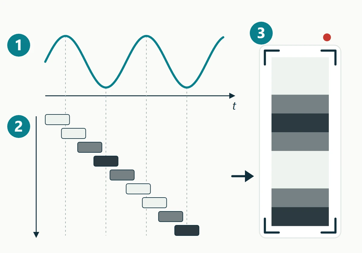
- A hypothetical light level rises and falls over time (t).
- Each sensor row collects light during its own exposure window, starting slightly after the row above. Each bar is shaded by how much light that row collected.
- In the recorded frame, rows that collected more light appear brighter, so a change over time becomes bands across the image.
A global shutter does not make the question disappear. In a global-shutter sensor, all pixels start and end their exposure together; the stored signal can then still be read out row by row (Teledyne Vision Solutions). That avoids the row-to-row exposure offsets responsible for this particular banding mechanism. It does not guarantee a band-free image, and time-varying light can still produce differences between frames.
Five quantities that are easy to mix up
Discussions of a banding video often go wrong because different timings are treated as one number.
| Quantity | What it describes | Where to find it |
|---|---|---|
| Display refresh rate (Hz) | How often the panel receives a new image | Host timing settings; module specification |
| Backlight drive or modulation (Hz, if any) | How the LED current behaves at a given brightness setting | Backlight driver datasheet and actual circuit configuration; optical measurement |
| Video frame rate (frames per second) | How many images the camera records per second | Camera or phone recording settings |
| Exposure time (seconds) | How long each row, or the whole frame, collects light | Camera settings or file metadata, if available |
| Row timing (seconds) | When each row’s exposure begins relative to the first row | Image sensor design; rarely exposed on phones |
None of these can be inferred from another. A 60 Hz refresh specification does not tell you the backlight’s behaviour. A “PWM” brightness input does not tell you either: Texas Instruments distinguishes drivers that switch LED current on and off from drivers that convert the PWM command into a steady analog current, and notes that switched current may run at a different frequency from the input signal (TI SNVA768). The emitted light depends on the driver architecture and how it is configured, not on the name of the control pin.
Counting bands in a video to calculate a frequency is also unreliable without knowing the sensor’s row timing and exposure. Phones rarely report those values, and messaging apps often re-encode the file.
What the video can and cannot establish
It can establish that, with that camera, mode and lighting, the recorded image of the screen area showed changing bands. If the effect stays inside the display area, investigate the display, its reflections, and how its image is sampled first; that localization does not isolate the cause.
It cannot establish:
- A defect. Recording artefacts under time-varying light can occur without any camera fault (Sony imaging support), and modulated light is not by itself a display fault. Whether the observed behaviour is out of specification depends on the module’s documentation and the application’s requirements.
- The source. Candidates include the backlight drive, the panel’s own refresh behaviour, the displayed content, and room lighting reflected in the cover glass. If similar bands also cross nearby surfaces, investigate room lighting and the camera as well; LED lighting can flicker at hundreds or thousands of cycles per second (Sony imaging support). This is a clue, not proof of an ambient-light contribution, and it does not clear the display.
- The frequency or waveform. The band pattern depends on the camera’s timing as much as on the light, as described above.
- A clean result. A video without bands shows only that this camera, at this setting, did not render the variation visibly. It is not evidence that the light output is constant.
- Comfort or safety. Neither the naked eye nor a phone camera is a calibrated flicker measurement. Nothing in a recording establishes compliance with a health or ergonomic requirement.
Change the recording first, and only one thing at a time
The useful first step is a controlled comparison, not a module swap. Keep the display exactly as it was: same host, same firmware, same test image, same brightness setting, same ambient lighting. Then change one camera parameter.
If the phone has a manual or “pro” video mode, change the exposure or shutter time and record again. If it does not offer manual control, record that limitation; switching between the phone’s standard frame-rate options is a weaker substitute, because the phone may change several parameters at once. A second camera can add context but is not a reference instrument.
If the pattern changes when only the recording condition changes, the appearance depends on the capture process. That result is consistent with exposure interacting with time-varying light, but does not establish the source or periodicity. For known flickering illumination, Sony describes fine shutter adjustment that reduces recorded bands (Sony imaging support). The same disappearance in an unexplained phone recording does not prove steady light output or qualify the display. No single shutter value suits all displays.
A second, separate comparison is to keep the camera settings fixed and change only the display brightness setting. Whether the bands change with brightness gives the supplier a clue about which part of the brightness control path to examine first. It does not identify the cause on its own.
When it stops being a camera question
Move to electrical and optical investigation when any of these apply:
- People see flicker, blanking or image disturbance without a camera.
- The image itself is corrupted, shifted or unstable rather than evenly brighter and darker.
- The behaviour follows a power event, temperature, cable movement or a firmware change.
- The product will be filmed, used on video calls, or viewed by a machine-vision camera, so recorded behaviour is part of the requirement.
The first three call for the broader checks in our TFT LCD flicker troubleshooting article, which covers power, timing, firmware, backlight and FPC paths. For backlight-related findings, our article on LCD backlight failure and brightness decay explains how drive conditions affect review.
The fourth is a requirements question. If cameras matter to the product, say so before samples are approved, and describe the cameras, frame rates and lighting involved. Any measurement of actual light modulation should use suitable optical equipment on the specific module, host settings and brightness levels, with test conditions recorded. Driver or circuit changes should stay within the module’s documented ratings and be agreed with the supplier, not improvised from a video.
What to send with a banding video
A supplier can reproduce and reason about the problem far faster when the video arrives with its context:
- The original video file, not a copy forwarded through a messaging app.
- Phone or camera model, recording mode, frame rate, and exposure or shutter setting if shown.
- A second clip of the same scene with one camera setting changed, and a note of what changed.
- Whether people see flicker without a camera, and whether bands appear outside the display area.
- Display module part number and revision, host board, firmware version and interface.
- Brightness setting, and how brightness is controlled in the product, if known.
- The displayed test pattern or screen content, and the room lighting type.
- How many units show it, and the steps to reproduce.
These details also belong in an incoming sample review; our LCD module sample validation checklist shows where they fit.
If you have a banding recording and the details above, you can send them for an LCD camera banding review. We can go through what the recording supports and what would still need to be measured.


