
Glass and enclosure
Position the display window against the minimum viewing area and review both glass outlines. Confirm the support method, contact compression and assembly clearances for the final construction.
Navigate
Rotate, zoom and inspect the product. Loads on request.
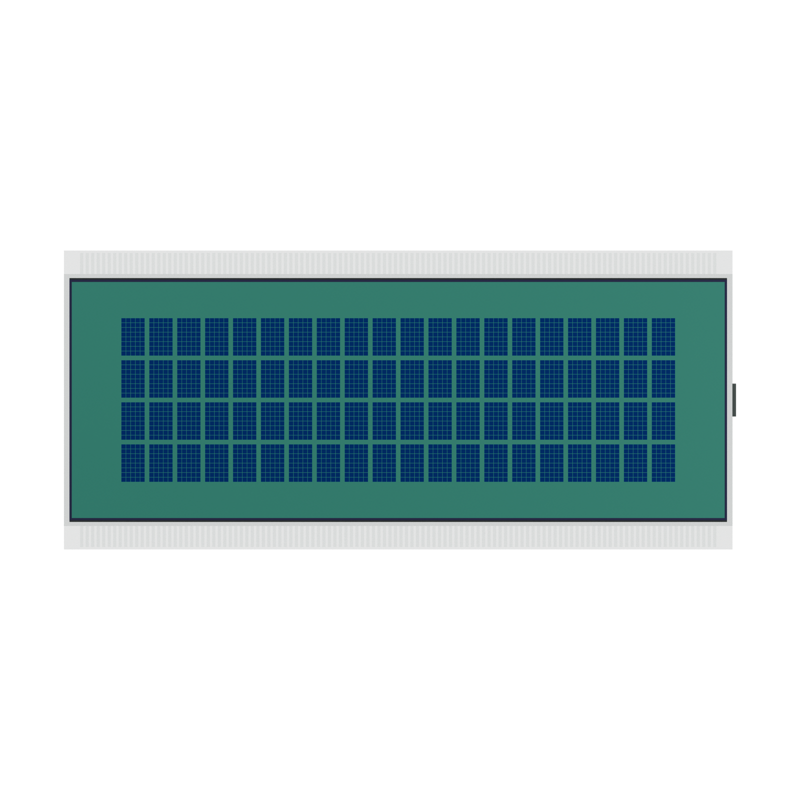
Front visualization of S4132D showing the screen layout and glass outline. Artwork, materials and fine geometry are visual references; final construction is confirmed for the OEM project.
OEM DISPLAY REFERENCE
S4132D is an STN positive-mode LCD glass reference with a 20 × 4 character layout. The reference uses ITO contact areas for a zebra connection, with a 77.30 × 26.00 mm minimum viewing area. Use the six views and 3D geometry to discuss the display window, glass support and electrical connection for your OEM design.
Images, 3D geometry and listed parameters are OEM reference information. Final dimensions, electrical requirements, optical configuration and construction are confirmed for your project.
01 / REFERENCE CONFIGURATION
A reference configuration for discussing your LCD project. Final specifications are subject to project confirmation.
| Model reference | S4132D |
|---|---|
| Display mode | STN, positive |
| Character format | 20 columns × 4 rows |
| Character cell | 5 × 8 dots |
| Large glass width × height | 85.00 ± 0.20 × 38.00 ± 0.20 mm |
| Small glass width × height | 85.00 ± 0.20 × 32.00 ± 0.20 mm |
| Minimum viewing area | 77.30 × 26.00 mm |
| LCD thickness | 2.90 mm maximum |
| Connection reference | Zebra elastomeric connector |
| ITO contact arrangement | 232 contacts: 116 on each of the two opposite edges |
| Contact pitch | 0.70 mm |
| LCD operating voltage | 4.5 V |
| Drive condition | 1/16 duty, 1/5 bias |
| Frame frequency | 64 Hz |
| Viewing direction | 6 o’clock |
| Front polarizer | Transmissive, adhesive |
| Rear polarizer | Transflective, adhesive |
| Operating temperature | −20 °C to +70 °C |
| Storage temperature | −30 °C to +80 °C |
02 / OEM DESIGN
Bring your requirements. We will review the configuration with you.
Position the display window against the minimum viewing area and review both glass outlines. Confirm the support method, contact compression and assembly clearances for the final construction.
Review the zebra connector arrangement, ITO contact mapping and LCD drive waveform together. Specify the host electronics separately; they are not established by the bare-glass rendering.
Confirm the viewing direction, illumination and readability under the intended conditions. Screen colour and contrast in the rendering are visual references rather than measured optical performance.
03 / APPLICATION DIRECTION
The 20 × 4 layout provides a reference for arranging text and numeric information. Define the character content and viewing conditions for your interface, then confirm the LCD driver, contact mapping and optical arrangement. The source does not establish an included PCB, controller or communication protocol.
04 / PRODUCT SUPPORT
The supplied model represents LCD glass with ITO contact areas. The source drawing specifies a zebra connection. Confirm the required PCB, LCD driver and connector assembly separately for your project.
The 3D model is a visual reference. The source drawing specifies a maximum LCD thickness of 2.90 mm. Use the agreed engineering drawing to confirm the final layer stack, fit and tolerances.
YOUR NEXT LCD PROJECT
Share your required display content, enclosure space, drive arrangement, operating environment and target quantity.


