
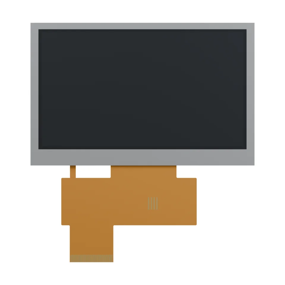
Rotate the product in your browser. Loads on request.
Drawing-based renderings. Surface finish and rear details are illustrative. Confirm the production drawing for integration.
4.3-INCH DISPLAY · RGB INTERFACE · NO TOUCH
4.3-inch 800 × 480
TFT LCD module
S-T430MBWS-01-W
A compact color display for OEM interfaces, with a 24-bit RGB connection, a 40-contact FPC and a 2.90 mm nominal module body.
Include your target quantity, application and sample timeline.
Check the display opening, unfolded FPC and host interface before selecting your enclosure or connector.
01 / AT A GLANCE
Product specifications.
Core specifications for an initial design review.
Request the applicable datasheet revision for electrical limits, operating temperature and design release.
| Display size | 4.3-inch diagonal |
|---|---|
| Resolution | 800 × 480 pixels, RGB |
| Display type | Transmissive TFT LCD |
| Interface | 24-bit parallel RGB |
| Driver IC | ST7262E43 |
| Touch panel | Not fitted |
| Module body (W × H × T) | 105.50 × 67.20 × 2.90 mm nominal |
| Active area (W × H) | 95.040 × 53.856 mm |
| Bezel opening (W × H) | 98.04 × 56.56 mm |
| Main FPC | 40 contacts · 0.50 mm pitch |
| Logic supply | 3.3 V typical |
| Luminance | 500 cd/m² typical, at 40 mA backlight current |
02 / MECHANICAL FIT
See how it fits.
Three dimensions to check before enclosure design.
Module envelope
Allow for the 105.50 × 67.20 mm body and 2.90 mm nominal thickness, plus cable routing and assembly clearance.
Active area & opening
The active area is 95.040 × 53.856 mm. The drawing’s 98.04 × 56.56 mm bezel opening is a separate measurement.
FPC routing
The main cable extends 45.56 mm below the body in the unfolded drawing. Confirm bend routing and connector orientation.
03 / DESIGN-IN CHECKS
Connect with confidence.
Match the host, power and cable before ordering samples.
Check your host interface
The module uses parallel RGB signals. Confirm pixel clock, synchronization, display enable and timing against the applicable datasheet.
Plan the power circuits
Logic power and LED backlight power have separate connections. Select the backlight driver using the confirmed voltage and current limits.
Match the FPC connection
Confirm 40 contacts, 0.50 mm pitch, contact side and cable thickness against your chosen connector drawing.
View connector signal groups 40-contact reference
| Contacts | Signal group |
|---|---|
| 1–2 | LED backlight: VLED_K / VLED_A |
| 3–4 | GND / VDD |
| 5–28 | R0–R7, G0–G7, B0–B7 |
| 29–34 | GND, DCLK, DISP, HSYNC, VSYNC, DE |
| 35–40 | NC, GND, NC (YU), NC (XL), NC (YD), NC (YR) |
Touch is not fitted. Do not treat the NC-labelled touch positions as a fitted touch interface. Confirm the full pin table before PCB release.
04 / APPLICATION IDEAS
A compact window into your equipment.
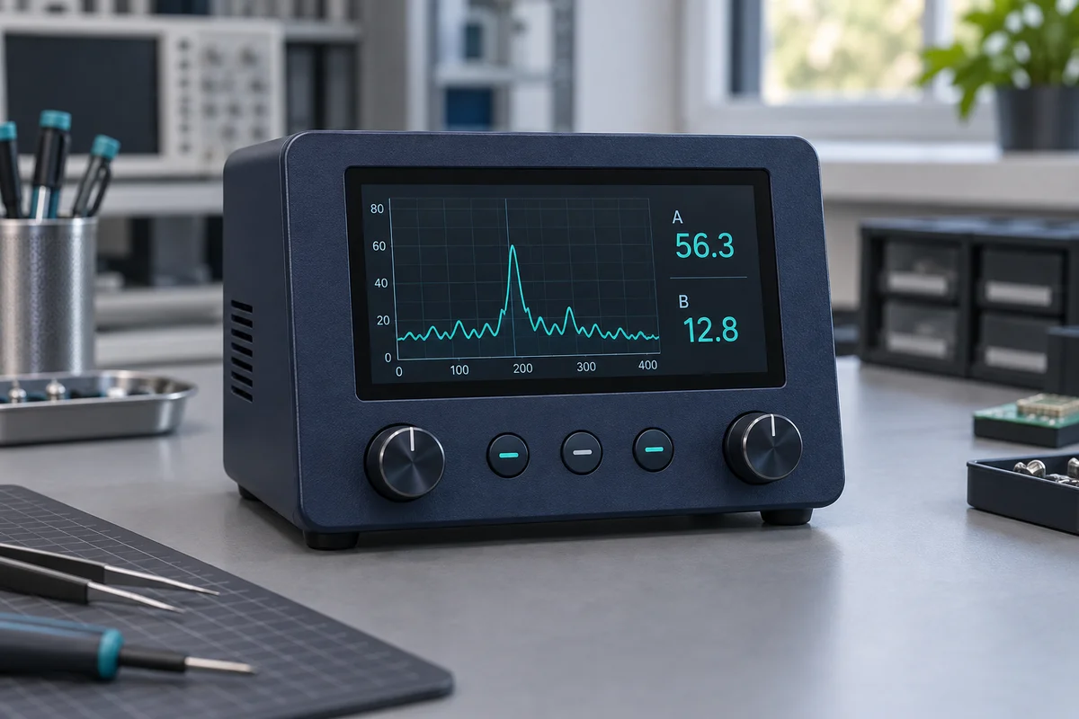
Consider this display for a color interface when your host supports RGB and your enclosure accommodates the module.
Equipment control panels
Present machine states, settings and operating menus.
Measurement instruments
Display readings, trends and configuration screens.
Embedded user interfaces
Explore a compact color UI for an RGB-capable host.
Suggested uses require system validation. Host board, enclosure, software and touch panel are not included.
05 / PRODUCT SUPPORT
Before you start a project.
Practical answers for purchasing and engineering teams.
Does this module include a touch panel?
No. S-T430MBWS-01-W is specified without a touch panel. If your interface needs touch, discuss the cover lens, touch technology and assembly requirements separately.
Can I connect it directly to HDMI or USB?
The module has a 24-bit parallel RGB interface. An HDMI or USB source needs a suitable interface board or host solution matched to the display timing and electrical requirements.
Can the 3D preview replace an assembly drawing?
The viewer provides a drawing-based exterior reference for visual review. Surface finish and rear construction are simplified. Use the confirmed mechanical drawing for mounting, tolerances and cable routing.
What should I send for a quotation?
Include S-T430MBWS-01-W, sample and production quantities, application, host interface and target schedule. Ask our team to confirm the current specification, availability, minimum order quantity and delivery timing for your project.
YOUR NEXT DESIGN STARTS HERE
Let’s check your display requirements.
Send the model, quantity and application to discuss your project.


