
Touch panel and cover lens
Custom Touch Panels And Cover Lenses For OEM Displays
Updated · Selection Guidance Reviewed.
Review resistive or projected capacitive touch, cover lenses and optical bonding with the display and host. Start from a published reference, then define the cover geometry, interface and use conditions that need validation.
Product paths
Choose The Front Stack Before Tooling
Touch performance depends on the full front structure: sensor type, cover lens, surface treatment, bonding method, controller interface and use environment.
Resistive Touch Panel
For single-touch input, stylus use, cost-sensitive products and industrial controls where pressure activation is acceptable.
Projected Capacitive Touch
For modern HMI, handheld devices and TFT display products that need multi-touch, clear optics and controller tuning.
Custom Cover Lens
For glass thickness, printed border, holes, corner radius, AG/AR/AF coating and enclosure fit requirements.
Optical Bonding
For outdoor readability, condensation control, impact support and reduced internal reflection in demanding projects.
Engineering scope
Touch And Cover Lens Details To Confirm
Before sample or tooling, define the touch structure, sensor IC, glass shape, surface treatment, bonding method and electrical interface.
- Touch structureRTP, PCAP, F+G, F+F, G+F, G+F+F or G+G stack direction.
- Cover lensGlass thickness, outline, holes, corner radius, printed border and logo area.
- Surface treatmentAG, AR, AF or combined treatment based on readability and touch feel.
- Bonding methodAir gap, perimeter bonding, OCA or LOCA optical bonding review.
- Controller interfaceI2C, USB, RS232 or project-specific touch controller requirements.
- Firmware tuningGlove touch, water rejection, noise handling and cover glass calibration.
- Display fitTFT active area, view area, bezel, FPC direction and mechanical clearance.
- Use environmentIndoor, outdoor, vehicle, medical, industrial or handheld conditions.
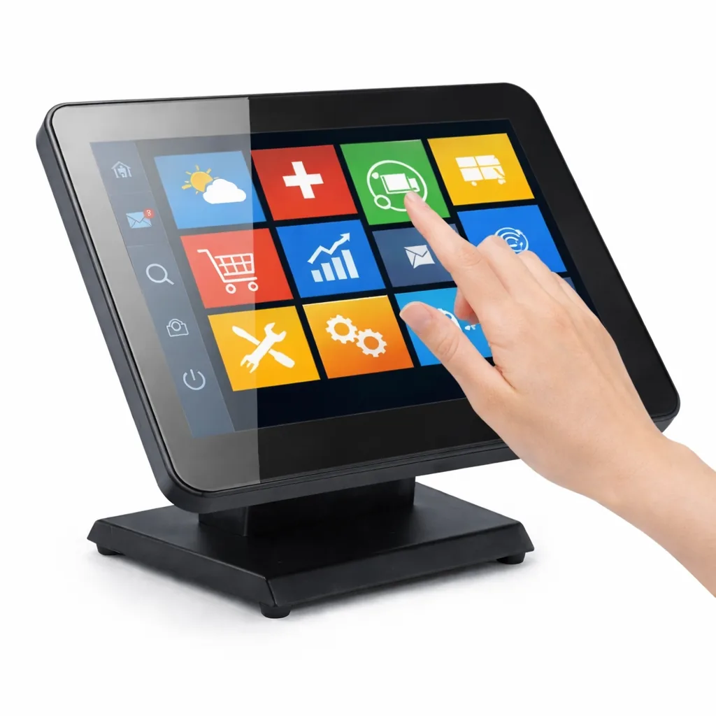
Touch structures
Common Touch Panel Stack Options
These structures are starting points. Final material, IC, FPC, cover lens and bonding details should be reviewed with the display module and product enclosure.
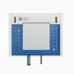
Film+Glass Resistive
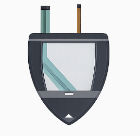
Film+Film Resistive
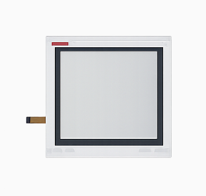
Flat Surface Resistive
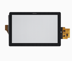
Glass+Film PCAP
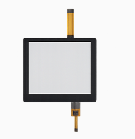
Glass+Film+Film PCAP
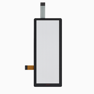
Glass+Glass PCAP
Selection guide
RTP, PCAP, Cover Lens Or Optical Bonding?
The right front stack depends on input method, optical target, mechanical risk and application environment.
| Project Need | Typical Direction | What to Confirm |
|---|---|---|
| Industrial control with simple input | F+G or F+F resistive touch panel | Actuation force, tail direction, connector, overlay size and operating environment. |
| Modern multi-touch HMI | G+F, G+F+F or G+G projected capacitive touch | Touch IC, I2C or USB interface, cover lens thickness, water and glove tuning. |
| Outdoor readability | Cover lens with AG/AR treatment and optical bonding review | Brightness, reflection target, bonding method, surface treatment and sunlight exposure. |
| Medical or cleaning-sensitive panel | Chemically strengthened cover lens with AF or other surface treatment | Cleaning agent exposure, coating area, glass thickness, edge treatment and enclosure fit. |
| Vehicle or rugged product | G+G PCAP, stronger cover lens and bonding review | Vibration, temperature, EMC noise, cover lens shape and lifecycle requirements. |
RFQ preparation
What To Send For Touch And Cover Lens Review
A useful request should define the display, touch layer, cover lens and product environment together.
Display And Mechanical Data
TFT size, active area, view area, cover lens outline, holes, corner radius, thickness and enclosure limits.
Touch And Interface Data
RTP or PCAP structure, touch IC preference, I2C, USB, RS232, pinout, FPC direction and controller board limits.
Optical And Environment Data
AG/AR/AF needs, optical bonding, outdoor use, glove touch, water exposure, EMC noise and expected volume.
Optical Bonding Vs Air Gap
Review bonding choices when outdoor readability, condensation or impact support matters.
Read bonding guideTFT LCD Module Fit
Start from display size, interface, brightness and mechanical constraints before confirming touch.
View TFT modulesLCD Sourcing Risks
Check supplier, lifecycle, brightness and integration risks before moving to production.
View checklistCheck The Touch Assembly In The Finished Device
For an embedded control panel, specify the display, touch sensor, cover lens, bonding and host together. Controller support and the assembled stack determine what must be tested.
| Requirement | Information To Provide | Check Before Approval |
|---|---|---|
| Host Connection | Controller, I²C or other required interface, supply, connector and software. | Confirm the pinout, driver, coordinate mapping and repeatable startup. |
| Gloves And Water | Glove material and thickness, water exposure and required interactions. | Test the intended controller settings with the final cover lens and enclosure. |
| Optical Bonding | Display and cover stack, viewing conditions, assembly constraints and service plan. | Agree the optical acceptance criteria and how a damaged layer would be repaired or replaced. |
| Noise And Cleaning | Power supply, grounding, nearby electronics, cleaning agents and cleaning method. | Check touch stability and material compatibility under the defined product conditions. |
Compare Integrated And Standalone References
S35001D is a 3.5-inch TFT with a separate I²C capacitive-touch connection. The 7-inch standalone capacitive touch reference has a published I²C / GT911 configuration and requires a separate display. They illustrate different assembly routes, not a matched pair.
Neither reference establishes glove, water, cleaning or EMC performance for your finished device. Define the required behavior and verify it with the project configuration.
Use the Optical Bonding Vs Air Gap Comparison to review readability and service trade-offs, or browse the standalone touch references before preparing your request.
Need A Touch Panel Or Cover Lens Direction?
Send your display drawing, touch structure, cover lens requirement, surface treatment and application environment. We will review the suitable front stack path.


