
TFT LCD White Screen After Power-On: Startup and Interface Diagnostics
Startup diagnostic
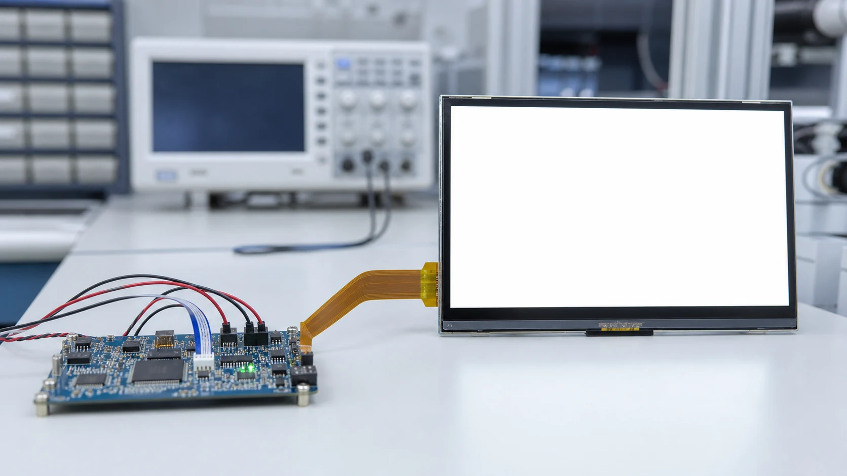
A uniform white screen after power-on can look like a failed display, but it often means the backlight has started while the display path has not reached a valid operating state. Start with the installed module and host evidence before changing the module.
What to do first
Record the exact part number, module documentation revision, host interface and startup behavior. Then distinguish a stable white screen from a dark screen, an intermittent flicker, a reset event and a contact-related failure. That classification prevents a mechanical replacement decision from hiding a timing, reset, power or interface issue.
On this page
Classify the symptom before changing hardware
Uniform white with backlight
Prioritize module-specific startup, reset, initialization, image-data and connection checks. A white field alone does not prove where the fault is.
Dark screen with no backlight
Keep this on a separate path. Check the power and backlight enable path before treating it as an interface-initialization symptom.
Image appears, then flickers or fails
Record the timing of the event and use the TFT LCD flicker diagnostic rather than merging it with a stable white-screen report.
Failure follows touch or enclosure contact
Preserve the event sequence and review possible ingress paths with the touch-triggered reset review.
Review the startup handoff in a controlled order
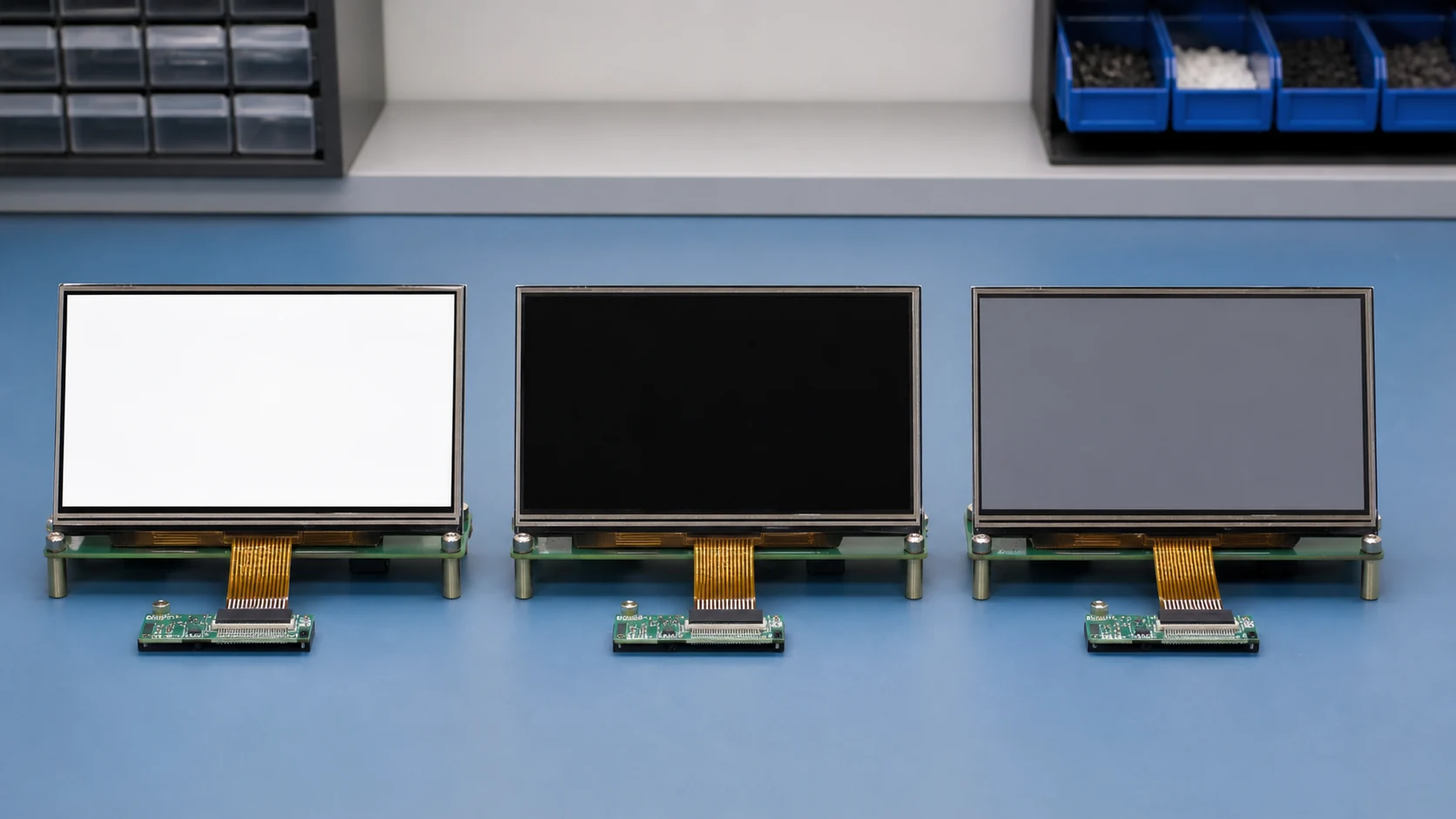
Different TFT LCD modules have different rail, reset, controller and interface requirements. The order below is therefore a review method, not a universal timing specification. The target module drawing and datasheet remain the authority.
- 1 Lock the exact module configuration Confirm the full part number, drawing and datasheet revision, interface variant, touch and cover configuration, and any board or FPC revision. Similar screen size or connector appearance is not enough to establish compatibility.
- 2 Check power and reset against the target document Review the required rails, enable behavior, reset polarity and startup sequence with the actual host board. Capture measurements only where your team can do so safely and compare them with the target document, not with a generic display example.
- 3 Verify interface initialization and image data Confirm the intended interface, pin assignment and configuration path. For RGB, LVDS, MIPI or SPI projects, use the TFT LCD interface guide for planning context, then validate the exact module-level settings and host implementation.
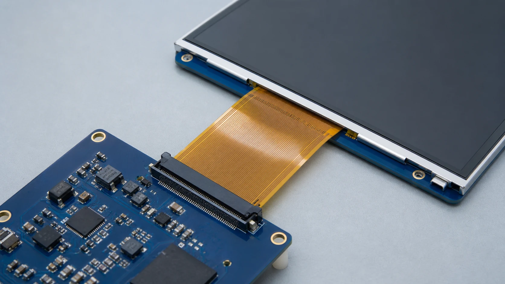
- 4 Inspect the installed FPC and connector route Compare connector orientation, contact side, pin assignment, FPC route, bend area, grounding arrangement and enclosure clearance against the approved assembly. The FPC and connector mismatch review explains why a mechanically mating connector can still be electrically wrong.
Use evidence that separates the module from the installed system
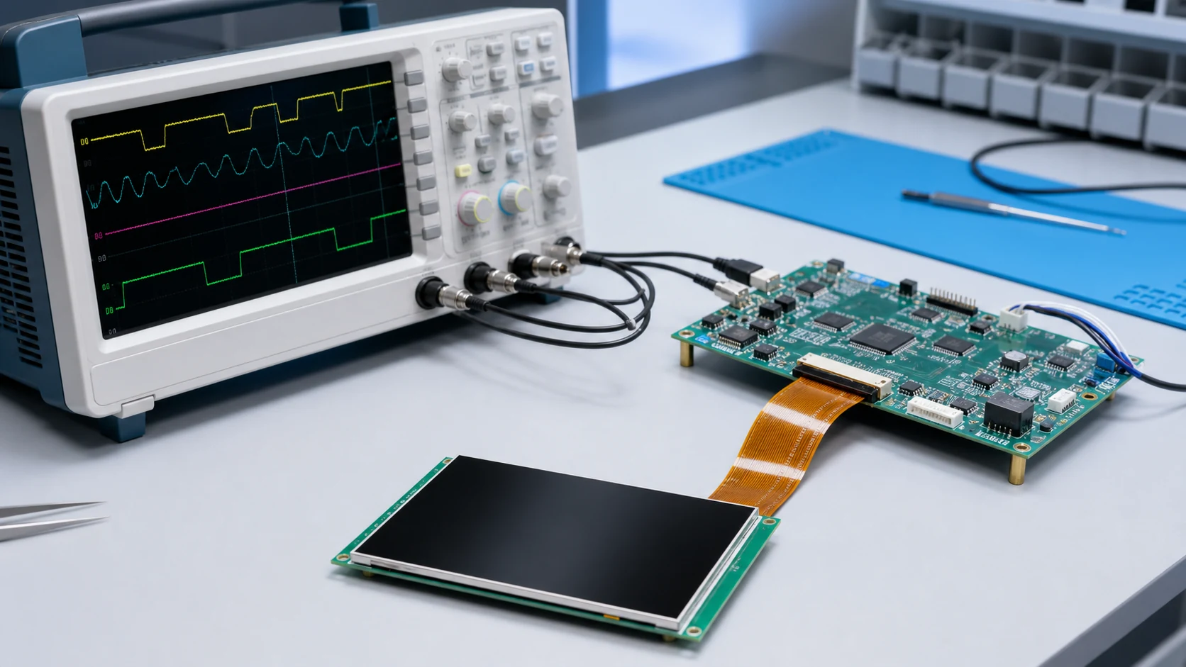
A replacement display can reproduce the same white screen if the host-board state, initialization, cable route or configuration is unchanged. Keep a controlled record of what was tested and what changed between trials.
| Observation | What it helps separate | Useful record |
|---|---|---|
| Backlight operates but no logo or image ever appears | A display-path or startup condition from a backlight-only condition | Power-on video, full module part number, host interface and software or configuration revision |
| Symptom changes after a controlled reset or startup change | An event linked to startup state from a constant cosmetic defect | Before-and-after sequence, reset observation and the target document revision |
| Symptom changes after FPC reseating or enclosure assembly | An installation path from an unchanged module condition | Clear connector and FPC photos, orientation, route and enclosure-clearance notes |
| Known system or module comparison is available | A single-variable comparison from a multi-variable replacement | What was held constant, what changed and the observed result |
As a document-review example, the COG-T144MHGS-07 module profile identifies an ST7735S controller, 8-bit MCU parallel interface and 20-pin signal map. Use the exact installed module documentation for startup limits; this example is not a universal power-on sequence.
Do not approve a replacement by size and connector alone
Replacement projects often begin with a panel that is physically similar to the original. That is a useful starting point, not a compatibility decision. Review the interface, host timing, power path, FPC direction, mechanical envelope and optical stack before sample approval. The LCD module drawing and specification review checklist provides the corresponding pre-sample review path.
Practical boundary
This article does not prescribe electrical values, reset widths or initialization commands. Those details are module- and controller-specific and must be taken from the approved documentation for the actual configuration.
Prepare this before an engineering review
A short, structured evidence package is usually more useful than a long description of a white screen. Include what you already have; missing measurements can be identified during the review.
- Module part number and label photos
- Drawing or datasheet revision
- Host interface and configuration summary
- Clear FPC and connector photos
- Startup video or symptom timeline
- Known changes to hardware, cable, firmware or enclosure
- Power and reset captures when they are available
- Whether the condition is repeatable and under which setup
Request a TFT LCD configuration review
For a white-screen, replacement or sample-approval question, send the module information, host interface, available drawings and symptom evidence. SuccessLCD can review the project configuration before a replacement or new sample path is chosen.
TFT LCD white-screen FAQ
Why does a TFT LCD stay white after power-on?
A uniform white screen can occur when the backlight is operating but the module has not received the required startup, reset, interface initialization, image-data or connection condition. The actual cause must be checked against the specific module documentation and host design.
Does a white screen prove that the TFT LCD module is faulty?
No. A white screen alone does not isolate the module. The same symptom can be related to startup sequencing, interface configuration, an incomplete FPC connection, host-board signal conditions or a module-level issue.
What evidence should be prepared for a white-screen review?
Provide the module part number, the relevant drawing or datasheet revision, the host interface, a startup sequence or capture when available, clear FPC and connector photos, the exact symptom and a short video if the display changes during boot.


